Method for restraining contraction in sintering ceramics under low temperature and prevent coating

A technology of sintering shrinkage and low-temperature sintering, which is applied to ceramic layered products, chemical instruments and methods, layered products, etc. The effect of avoiding pollution

Inactive Publication Date: 2003-10-08
YAGEO CORP
View PDF3 Cites 4 Cited by
  • Summary
  • Abstract
  • Description
  • Claims
  • Application Information

AI Technical Summary

Problems solved by technology

The first method of this invention is to use the force generated by the fixture to suppress the shrinkage during sintering. However, due to the uneven distribution of load and pressure, it is easy to cause shrinkage of the ceramic structure, which in tur

Method used


Image

  • Method for restraining contraction in sintering ceramics under low temperature and prevent coating
  • Method for restraining contraction in sintering ceramics under low temperature and prevent coating
  • Method for restraining contraction in sintering ceramics under low temperature and prevent coating

Examples


Embodiment 1

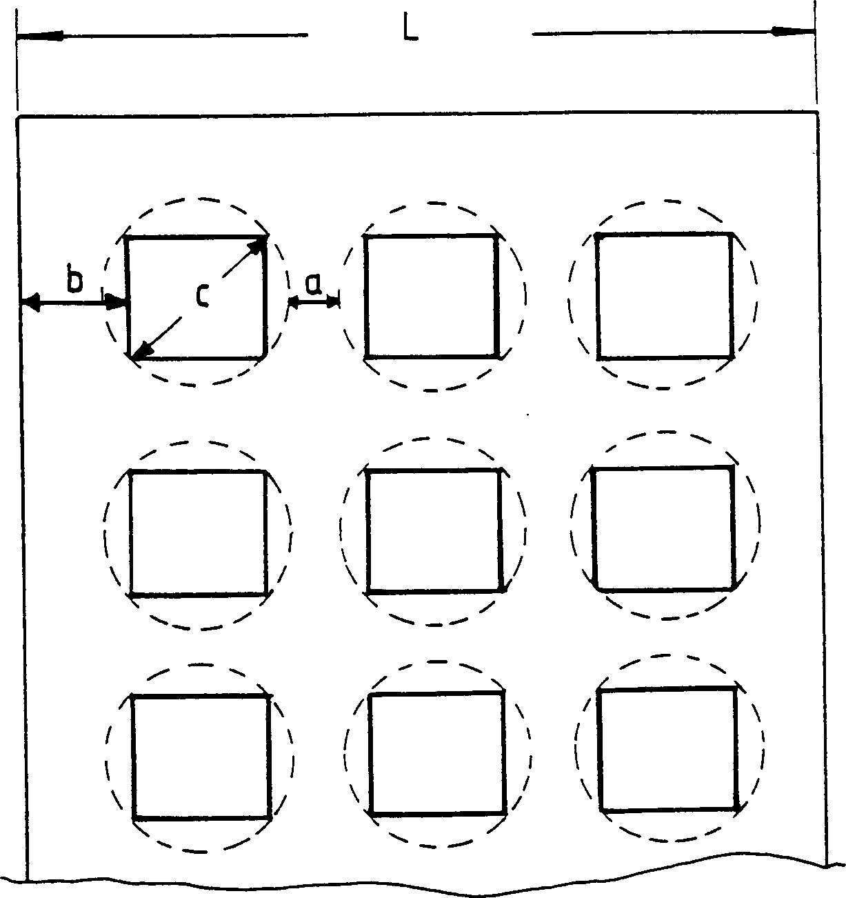
[0052] Fill the ceramic raw material Ca-AlSi or the inhibition layer material alumina and borosilicate glass raw materials into the barrel, add water to the barrel and maintain a solid content of about 65wt%, and make the average particle size by rolling with 2mmYTZ balls The diameter is about 0.8 μm. Further add organic adhesive (PVA) and plasticizer (PEC) and use a scraper to form a ceramic green body with a thickness of about 80 μm and a thickness of L 1 the inhibition layer. In this embodiment, the holes on the suppression layer are directly formed by punching holes. The positions of the holes are for printing electrodes. Each hole is a square of 1 cm × 1 cm. The distance between each hole is is 0.65 cm, and the distance between the outermost perforation and the edge of the inhibition layer is 1.2 cm.

[0053] The designed circuit pattern is printed on the ceramic green body to become an electrode layer. The above-mentioned printed ceramic green body and the inhibition ...


PUM


Abstract

A method for suppressing the low-temp sinter shrinkage of ceramic features that a suppressing layer is applied to the raw ceramic blank with heterogous material, said suppressing layer is perforated at the positions correspondent to said heterogous material, and the size of hole and the gap between holes, must meet a certain condition.

Description

field of invention [0001] The present invention relates to a method for suppressing the sintering shrinkage of low-temperature ceramics, through the use of a specific suppressing layer with perforated holes, which can effectively suppress the shrinkage in the X-Y direction of low-temperature ceramics sintering, but without the removal steps or steps required by the prior art after firing Problems that affect the flatness of the ceramic surface, thereby reducing the process and cost, and can produce high-quality, multi-layer ceramic products. Background of the invention [0002] In order to meet the light, thin and small requirements of today's electronic related products, the interconnected circuit board manufacturing process has become a must. This interconnected circuit board is a circuit that can be electrically or mechanically connected to each other, or a secondary system formed by extremely small circuit components. Usually, it can be combined with different forms of c...

Claims


Application Information

Patent Timeline
IPC IPC(8): B32B18/00C04B35/64C04B41/89
Inventor 李文熙苏哲仪李俊德饶瑞珠
Owner YAGEO CORP
Why Eureka
Try Eureka