Method for controlling power supply to current vertex decelerator

A technology of eddy current retarder and power supply control, which is applied in the direction of control system, electromechanical brake control, electrical components, etc., which can solve the problems of increased energy consumption of automobiles, and achieve the effects of reduced magnetic flux loss, reduced volume, and reduced electrical load

Inactive Publication Date: 2003-10-08
WANXIANGQIANCHAO CO LTD
View PDF1 Cites 0 Cited by
  • Summary
  • Abstract
  • Description
  • Claims
  • Application Information

AI Technical Summary

Problems solved by technology

This not only brings high-power heat dissipation requirements to the control design, but also leads to an increase in vehicle energy consumption

Method used


Image

  • Method for controlling power supply to current vertex decelerator
  • Method for controlling power supply to current vertex decelerator

Examples


Embodiment 1

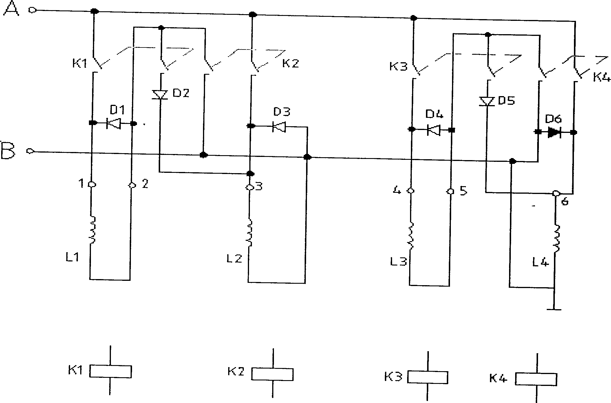
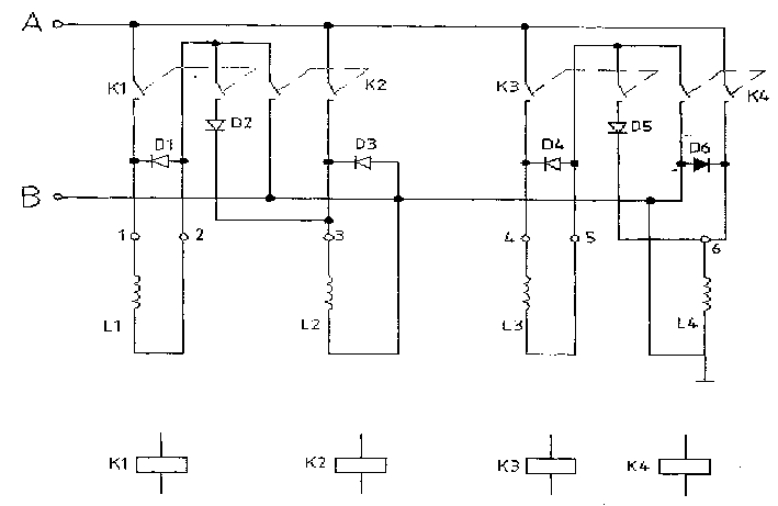
[0007] Example 1: Press figure 1 Shown is a schematic circuit diagram of the switching circuit of an actual embodiment, which has been simplified to a certain extent according to the actual situation. It is connected to a lowest power range and adopts a control mode of two sets of excitation coils in series. There are retarder coils L1, L2, L3 and L4, switching diodes D2 and D5, freewheeling absorption diodes D1, D3, D4 and D6, double contact relays K1, K2, K3 and K4, through the control of double contact relay K1 , K2, K3 and K4 are opened and closed, and the retarder coils L1, L2, L3 and L4 are combined to form different series and parallel connections. When K1 or K3 pulls in, L1 and L2 are connected in series or L3 and L4 are connected in series. When K1 and K3 are pulled in at the same time, L1 and L2 are connected in series, and after L3 and L4 are connected in series, the two are connected in parallel. When K1, K2, and K3 are pulled in at the same time, L1 and L2 are connect...


PUM


Abstract

A method controls the magnetide of brake moment in slow speed by changing the magnitude of current vortex. Combining connection modes of windings at the current vortex declerator in serial or parallel controls the magnitude of current at the current vortex decelerator. The invented control method can use minor current in low-end levels to get same shockless braking moment with less size of the decelerator and more control levels.

Description

Technical field [0001] The invention relates to a power supply control method for an eddy current retarder, in particular to a power supply control method for controlling the size of the retarder braking torque by combining the connection mode of the working coil on the eddy current retarder. Background technique [0002] The eddy current retarder uses the stator magnetic field to generate eddy currents in the rotor to achieve the effect of non-contact retarding braking. In order to achieve the torque control when retarding, two methods are currently used: one is the widely used grouping parallel connection The connection method is to divide the stator coils into several groups in parallel and energize them separately. As the number of energized coil groups increases, a retarding torque (braking torque) proportional to the number of energized coils is obtained. In this way, relays are often used to control the connection and disconnection of the coils. Take an eddy current retard...

Claims


Application Information

Patent Timeline
Patent Type & Authority Applications(China)
IPC IPC(8): H02P15/00
Inventor 方国平王修强曾雄宇
Owner WANXIANGQIANCHAO CO LTD
Why Eureka
Try Eureka