Chain tensioner

A technology of applying device and tensioning force, applied in the direction of transmission, belt/chain/gear, machine/engine, etc., can solve problems such as partial wear

Inactive Publication Date: 2003-10-15
TSUBAKIMOTO CHAIN CO
View PDF0 Cites 8 Cited by
  • Summary
  • Abstract
  • Description
  • Claims
  • Application Information

AI Technical Summary

Problems solved by technology

In addition, this component produces such deviation loads F1 and F2 as shown in FIG. 10, and has the problem that local partial wear tends to occur when the housing 530 is made of aluminum material.

Method used


Image

  • Chain tensioner
  • Chain tensioner
  • Chain tensioner

Examples


Embodiment Construction

[0035]Preferred embodiments of the chain tension applying device according to the present invention will now be described with reference to the accompanying drawings.

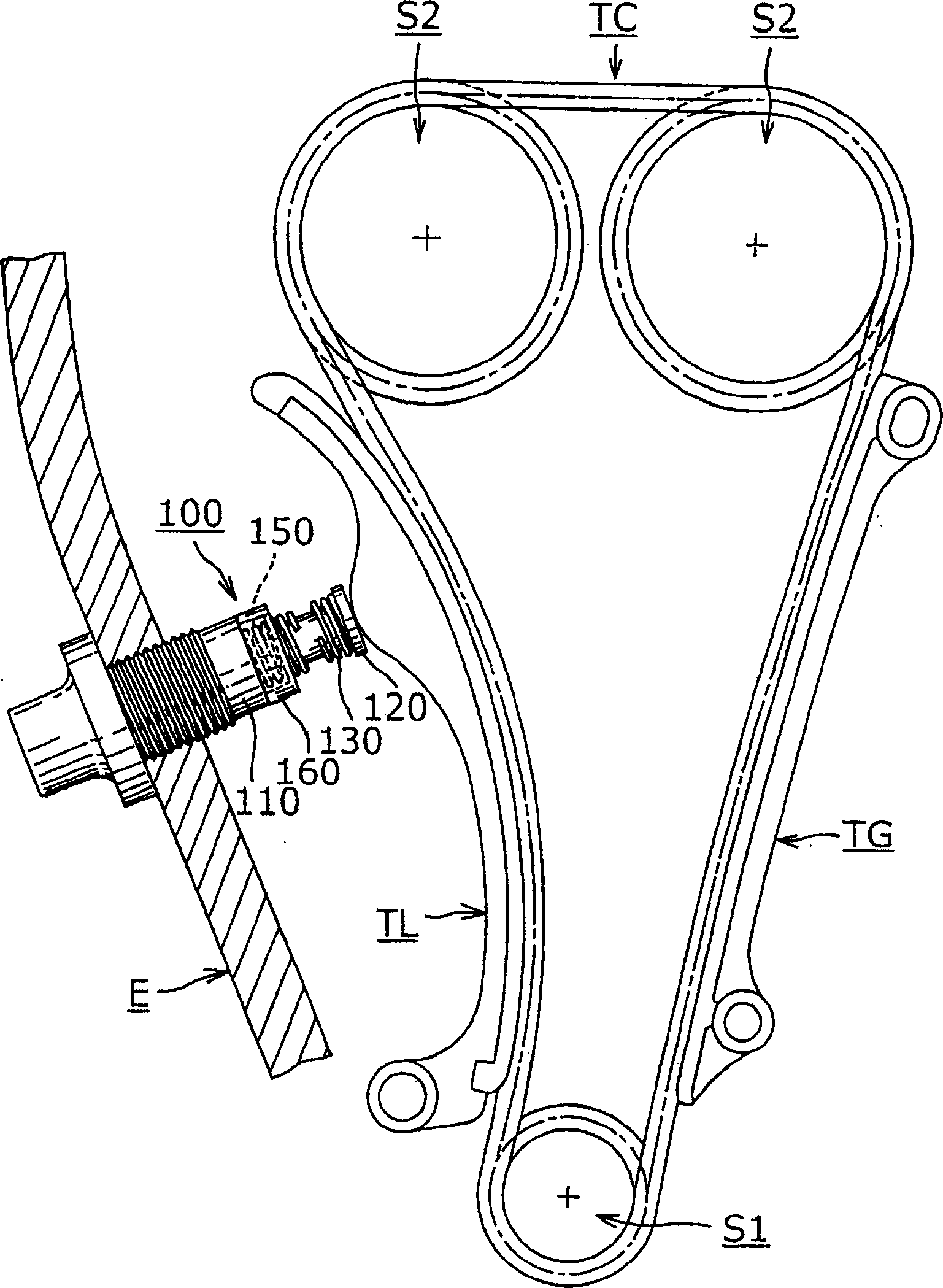
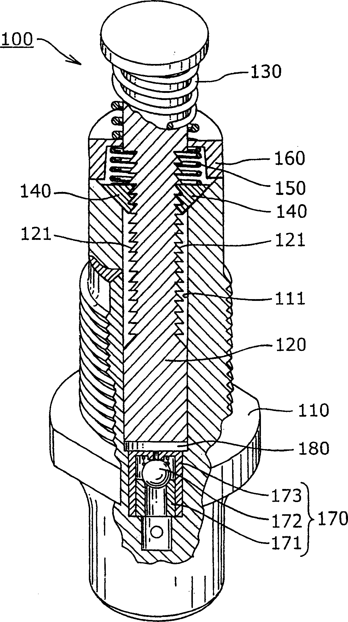
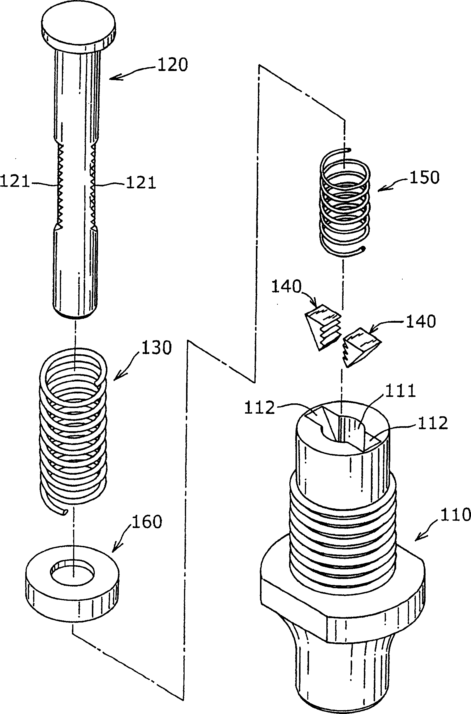
[0036] First, the chain tension applying device 100 of the first example of the present invention will be described. figure 1 is a structural diagram of a chain tension applying device according to a first example of the present invention, figure 2 yes figure 1 A partial sectional schematic diagram of the chain tensioning force application device shown, image 3 yes figure 1 An exploded view of the chain tensioning device shown and its assembled view, Figure 4(a)-4(c) yes figure 1 The working explanatory diagram of the shown chain tension applying device, specifically, Fig. 4(a) is a view showing the state just before exerting the check function, and Fig. 4(b) is a view showing the moment when the check function is released. The view of the state, and Figure 4 (c) is a view showing the state when the plu...


PUM


Abstract

Provided is a chain tension applicator which can play wear resistance function by dispersing and reducing load imparted from a plunger at backstop and reducing processing accuracy and processing load (needed) during component machining and assembling period. A chain tension applicator includes: a plunger 120 protruding to a drive chain; a housing 110 having a plunger slide hole 111 in which the plunger 120 forms a protrusile insert cooperation; a protruding bias spring 130 of the bias plunger 120; a pair of wedge-shaped cams 140, 140 engaged on two racks 121, 121, the racks 121, 121 are formed at an opposite position where the outer circle of the plunger 120 is divided into at least two parts. The wedge-shaped cams 140, 140 are embedded with space on a cam slide seat 112 which is gradually becoming thin and is formed on the front end side of the opening of the plunger slide hole 111.

Description

technical field [0001] The present invention relates to a chain tension applying device for applying an appropriate tension to a power transmission chain arranged in an automobile engine, and the chain tension applying device is particularly called a chain tensioner for a timing chain , the timing chain transmits rotation between the sprocket on the crankshaft side and the sprocket on the camshaft side. Background technique [0002] A conventional chain tensioning device known as a tensioner has a structure in which a plunger protruding from a housing presses the back surface of the tensioner lever brake shoe surface of the tensioner lever; A conventional chain tensioning device utilizes a plunger protruding from a housing to slide into contact with the slack side of the chain by squeezing the back surface near the rotating end of a tensioner lever that is rotatably supported to the engine body side; so the brake shoe surface of the tensioner lever is in sliding contact wit...

Claims


Application Information

Patent Timeline
Patent Type & Authority Applications(China)
IPC IPC(8): F02B67/06F16H7/08
CPCF16H2007/0859F16H2007/0853F16H2007/0812F16H2007/0806F16H7/0848
Inventor 吉田修桥本裕至
Owner TSUBAKIMOTO CHAIN CO
Why Eureka
Try Eureka