Steam releasing device for pressure cooker

A technology of a discharge device and a pressure cooker, applied in the field of pressure cookers, can solve the problems of being difficult to keep clean, unable to remove condensed water, etc., and achieve the effect of clean use

Inactive Publication Date: 2003-10-22
LG ELECTRONICS (TIANJIN) APPLIANCES CO LTD
View PDF0 Cites 68 Cited by
  • Summary
  • Abstract
  • Description
  • Claims
  • Application Information

AI Technical Summary

Problems solved by technology

[0013] Moreover, because the existing steam cover (20) gathers the condensed water in its inner space (21'), because it cannot be observed from the outsi

Method used


Image

  • Steam releasing device for pressure cooker
  • Steam releasing device for pressure cooker
  • Steam releasing device for pressure cooker

Examples


Embodiment Construction

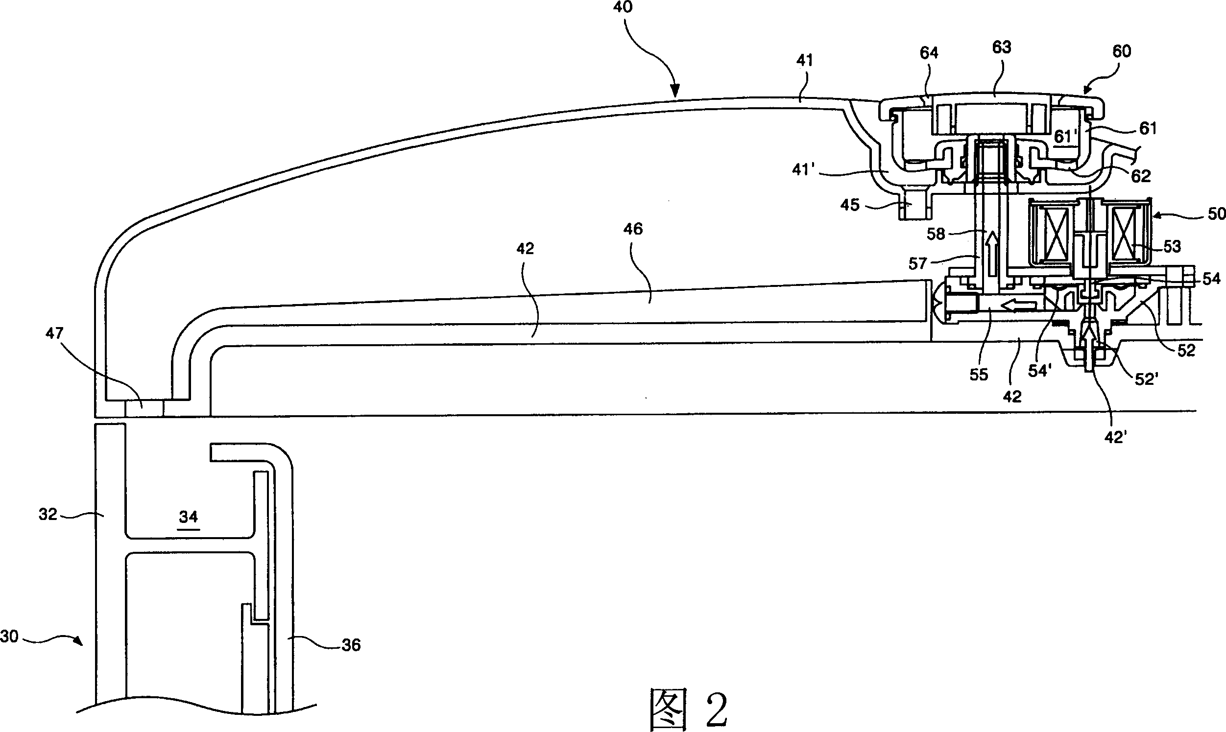
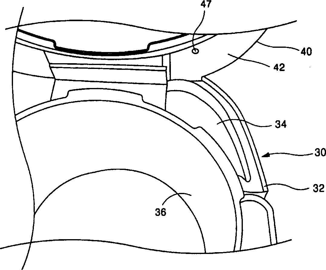
[0026] Figure 2 and image 3 Shown, pressure cooker is made of body (30) and pot cover (40). The body (30) includes a cooking pot (36) that provides space for cooking. The pot cover (40) is contained in the upper end of the body (30), and communicates with the outside selectively to the inside of the cooking pot (36).

[0027] Such as image 3 Shown, in body (30) inside, be provided with a space that can lay rice cooker (36). Loam cake (32) body (30) upper end. On the top side of the upper cover (32), a condensed water storage part (34) is provided. The condensed water storage part (34) becomes the collection and storage part of the condensed water mixed in the steam discharged from the cooking pot (36) during the cooking process or after the cooking is finished, and is arranged in the space above the upper cover (32) . Moreover, the upper part of the condensed water storage part can be opened, and the user can see it by lifting the pot cover (40).

[0028] The pot cove...


PUM


Abstract

The steam releasing device of pressure cooker includes cooker cover inner plate with steam releasing outlet, valve with by-pass steam channel, releasing pipe communicated with by-pass steam channel of valve and steam releasing portion formed from steam cover with steam releasing hole, on the steam cover a condensate storage portion is set, and said condensate storage portion is equipped with condensate discharge outlet, and on the top cover of cooker cover positioned under the condensate discharge outlet a water discharge hole is set, and the upper portion of the pressure cooker is equipped with water-accumulating portion, and in the interior of cooker the lower portion of condensate storage portion is equipped with a condensate guide portion for guiding the condensate into the described water-accumulating portion.

Description

technical field [0001] The invention relates to a pressure cooker, in particular to a steam discharge device of the pressure cooker. Background technique [0002] figure 1 It is a pressure cooker steam discharge device in the prior art. As shown in the figure, the steam discharge device in the prior art is a solenoid valve, which is generally installed on the pot cover, and selectively separates and communicates with the outside of the cooking space inside the pressure cooker. [0003] That is: on the discharge port (2) that passes through the pot cover inner plate (1), a valve body (5) is installed to communicate with the discharge channel (6). Between the valve body (5) and the inner plate (1) of the pot cover, a seal and an O-ring are housed to prevent leakage. In the inside of the valve body (5), due to being close to the dividing plate (17), an internal air channel (5') is formed. [0004] Inside the valve body (5), a bypass air passage (7) is provided and communica...

Claims


Application Information

Patent Timeline
IPC IPC(8): A47J27/08A47J27/09A47J36/38
Inventor 李基成
Owner LG ELECTRONICS (TIANJIN) APPLIANCES CO LTD
Why Eureka
Try Eureka