

Cross flow fan
A technology of cross-flow fans and fans, which is applied to the components of pumping devices for elastic fluids, non-variable-capacity pumps, machines/engines, etc., to prevent mutual influence, improve performance, and reduce noise.
- Summary
- Abstract
- Description
- Claims
- Application Information
AI Technical Summary
Problems solved by technology
Method used
Image

Examples
Embodiment approach 1
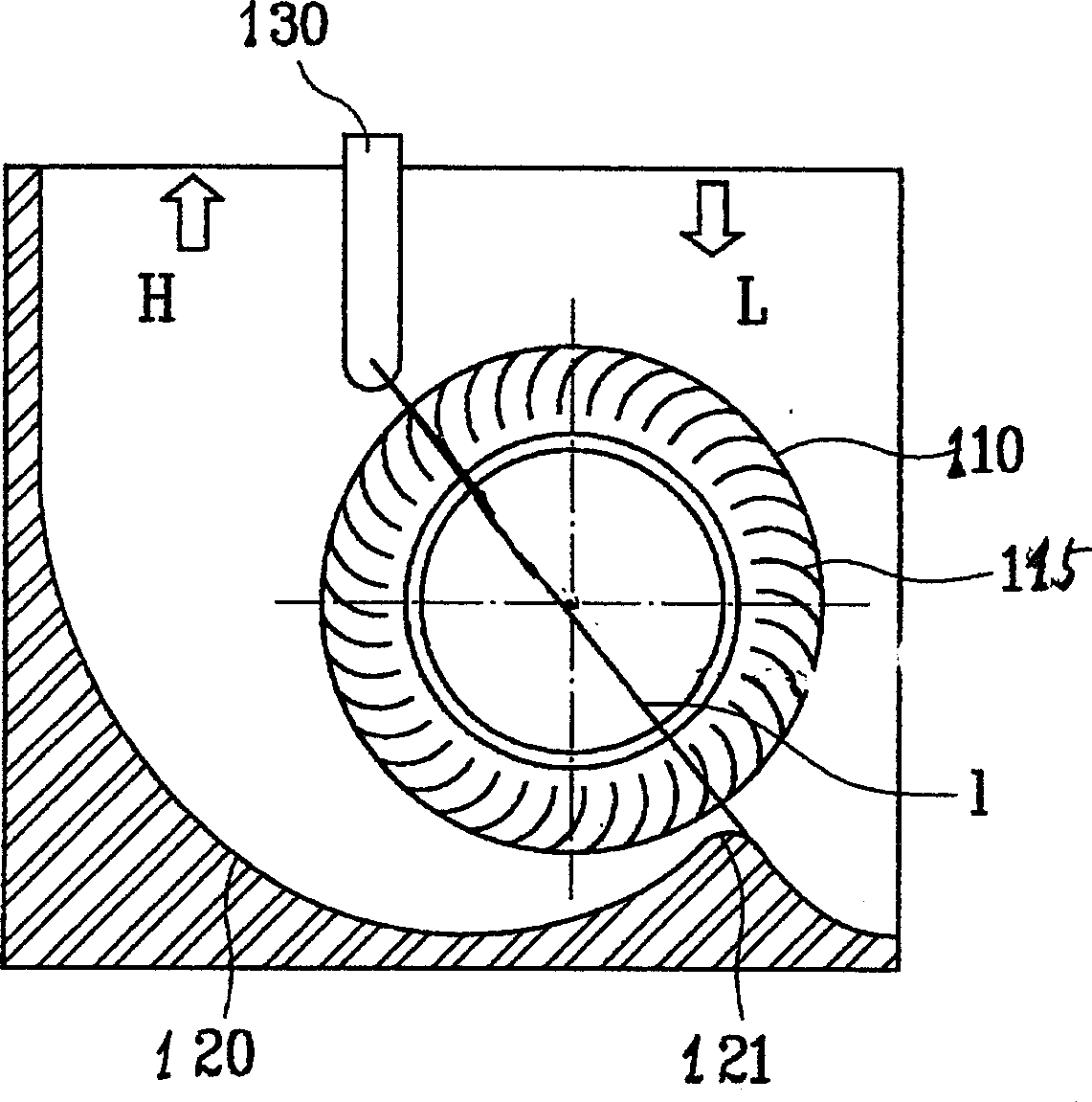
[0031] like Figure 2a and Figure 2b As shown, the cross-flow fan of the present invention includes: an impeller component 110 , a motor (not shown in the figure), a rear guide surface 120 , a boundary plate 113 , a stabilizer 130 and an exhaust guide plate 140 .
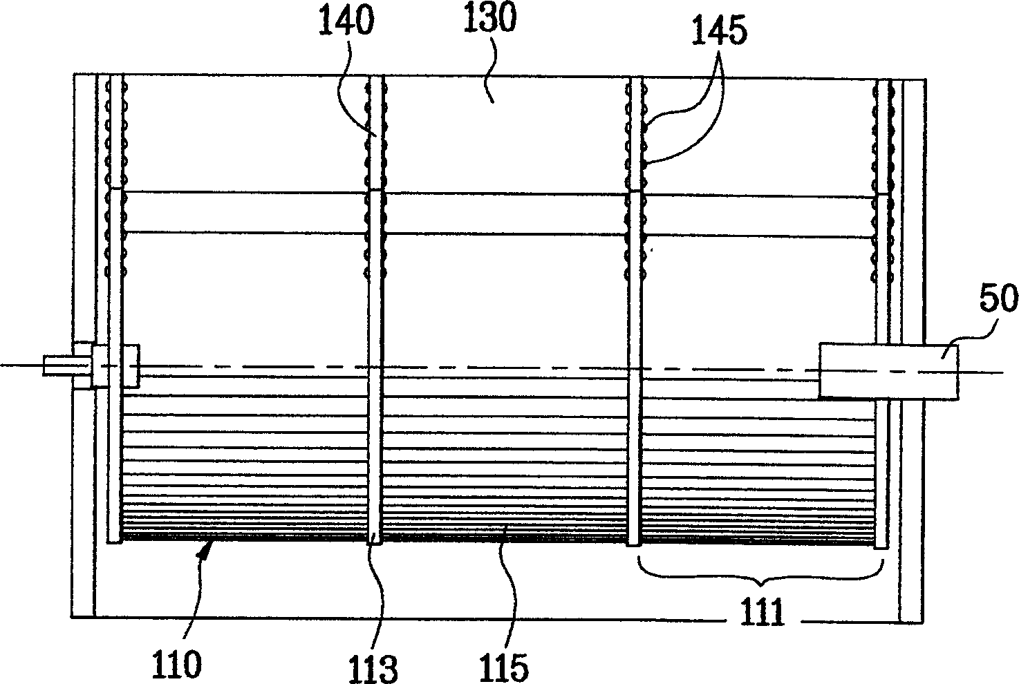
[0032] The impeller part 110 includes: 3 unit fans 111 connected in series by annular boundary plates, and each unit fan 111 includes several blades 115 curved along the rotation direction and arranged at equal intervals; the rotating shaft of the impeller part 110 is connected with the motor The crankshaft 50 is connected.
[0033] The rear guide surface 120 is arranged at the rear part of the impeller component casing to form a discharge flow path for sucked air. One side of the rear guide surface 120 is provided with a gap part 121, and the gap part 121 is formed along the axial direction; the stable The device 130 is arranged on one side of the impeller housing along the axial direction, and together with the...
Embodiment approach 2
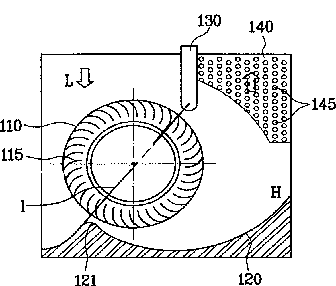
[0038] like image 3 As shown, the cross-flow fan of the present invention includes: an impeller component 110 , a motor (not shown in the figure), a rear guide surface 120 , a boundary plate 113 , a stabilizer 130 and an exhaust guide plate 140 .
[0039] The impeller part 110 includes: 3 unit fans 111 connected in series by annular boundary plates, and each unit fan 111 includes several blades 115 curved along the rotation direction and arranged at equal intervals; the rotating shaft of the impeller part 110 is connected with the motor The crankshaft 50 is connected.
[0040] The rear guide surface 120 is arranged at the rear part of the impeller component casing to form a discharge flow path for sucked air. One side of the rear guide surface 120 is provided with a gap part 121, and the gap part 121 is formed along the axial direction; the stable The device 130 is arranged on one side of the impeller housing along the axial direction, and together with the gap part 121 form...
Embodiment approach 3
[0045] like Figure 4 As shown, the cross-flow fan of the present invention includes: an impeller component 110 , a motor (not shown in the figure), a rear guide surface 120 , a boundary plate 113 , a stabilizer 130 and an exhaust guide plate 140 .
[0046] The impeller part 110 includes: 3 unit fans 111 connected in series by annular boundary plates, and each unit fan 111 includes several blades 115 curved along the rotation direction and arranged at equal intervals; the rotating shaft of the impeller part 110 is connected with the motor The crankshaft 50 is connected.
[0047] The rear guide surface 120 is arranged at the rear part of the impeller component casing to form a discharge flow path for sucked air. One side of the rear guide surface 120 is provided with a gap part 121, and the gap part 121 is formed along the axial direction; the stable The device 130 is arranged on one side of the impeller housing along the axial direction, and together with the gap part 121 for...
PUM
 Abstract
Description
Claims
Application Information