Uninterruption power source integrated with switch power

A switching power supply, power supply technology, applied in battery circuit devices, current collectors, electric vehicles, etc., can solve the problems of large size and weight of uninterruptible power supply, high manufacturing cost, low inverter efficiency, etc., to improve inverter efficiency and The effect of working stability, reducing production cost and simplifying the circuit

A switching power supply, power supply technology, applied in battery circuit devices, current collectors, electric vehicles, etc., can solve the problems of large size and weight of uninterruptible power supply, high manufacturing cost, low inverter efficiency, etc., to improve inverter efficiency and The effect of working stability, reducing production cost and simplifying the circuit

CN1452290AInactive Publication Date: 2003-10-29曲峰

Image

  • Uninterruption power source integrated with switch power
  • Uninterruption power source integrated with switch power

Examples


Embodiment Construction

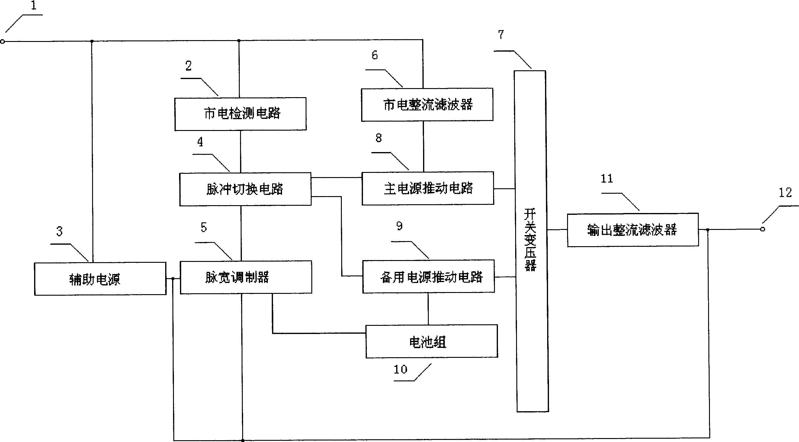
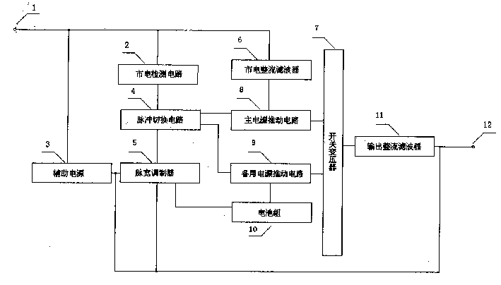
[0009] The present invention will be further described below in conjunction with accompanying drawing:

[0010] 1 is the mains input terminal,

[0011] 2 is a commercial power detection circuit, which is connected with the commercial power input terminal 1 and the pulse switching circuit 4 . Its function is to detect whether the commercial power supply is normal, and to provide switching signals to the pulse switching circuit 4 .

[0012] 3 is an auxiliary power supply, which is connected with the mains input terminal 1 and the pulse width modulator 5, and its function is to supply power for the pulse width modulator 5.

[0013] 4 is a pulse switching circuit, which is connected with the pulse width modulator 5, the main power supply driving circuit 8, and the standby power supply driving circuit 9. The pulse signal of the pulse width modulator 5 is delivered to the main power supply driving circuit 8, and the pulse signal of the pulse width modulator 5 is delivered to the s...


PUM


Abstract

A switching power supply integrated UPS is characterized by that the power supply of electric appliance is integrated with UPS for sharing a single PWM and switching transformer by primary power supply and standby power supply and directly converting the voltage of battery to the voltage needed by electric appliance. Its advantages are small size, light weight, simple circuit and low cost.

Description

Technical field [0001] The invention belongs to the category of uninterruptible power supply. technical background [0002] The current uninterruptible power supply, one is to convert the voltage of the battery into AC mains voltage, and then supply it to electrical appliances. The voltage required by the electrical appliance is converted from the power supply of the electrical appliance to the electrical appliance. The disadvantage is: after the energy of the battery is converted twice, the inverter efficiency becomes very low. Moreover, the conversion link is added, which reduces the working stability, has large volume and weight, and high manufacturing cost. [0003] One is to convert the battery voltage into the DC voltage required by the power input of the electrical appliance, and generate the voltage required by the electrical appliance from the power supply of the electrical appliance, or connect it in parallel with the power supply of the electrical appliance to p...

Claims


Application Information

Patent Timeline
29 Oct 2003
Publication
CN1452290A
IPC
H02J7/00
Inventors
曲峰