Air flow guide apparatus for microwave oven

A technology of air flow guidance and microwave ovens, which is applied in the field of microwave ovens, can solve the problems of complicated production and assembly, complex structure, and difficult production, and achieve the effects of simple structure, improved production efficiency, and reduced production costs

Inactive Publication Date: 2003-11-12
LG ELECTRONICS (TIANJIN) APPLIANCES CO LTD
View PDF0 Cites 5 Cited by
  • Summary
  • Abstract
  • Description
  • Claims
  • Application Information

AI Technical Summary

Problems solved by technology

[0006] To sum up, the existing guide mechanism introduces the airflow generated in the blower fan 14 into the heating chamber, and its structure is relatively

Method used


Image

  • Air flow guide apparatus for microwave oven
  • Air flow guide apparatus for microwave oven
  • Air flow guide apparatus for microwave oven

Examples


Embodiment Construction

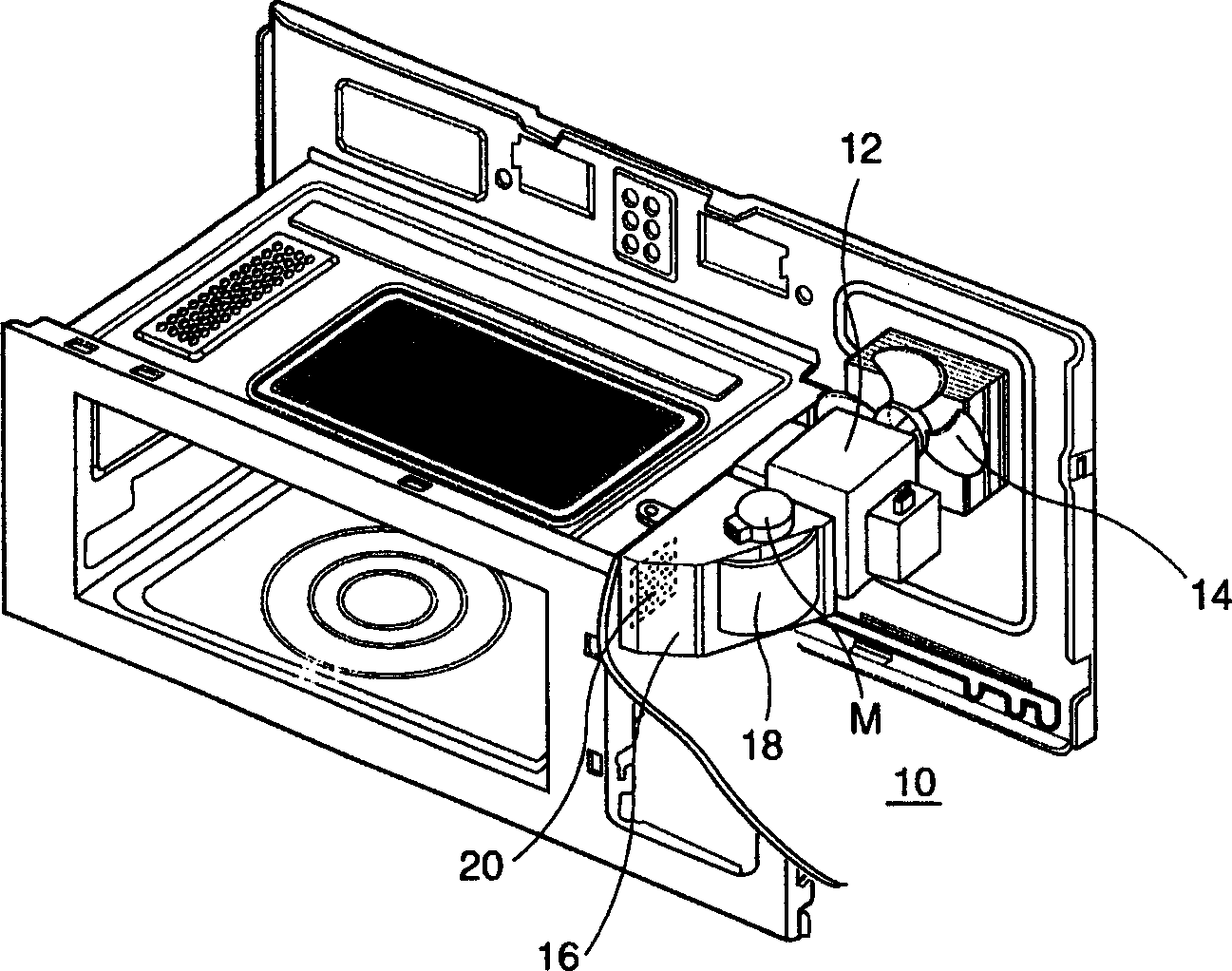
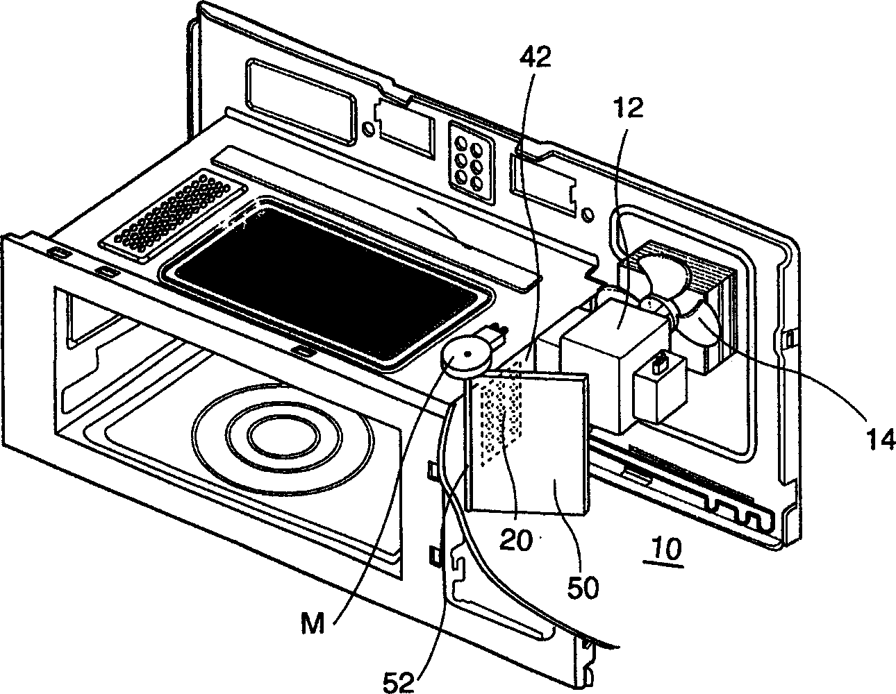
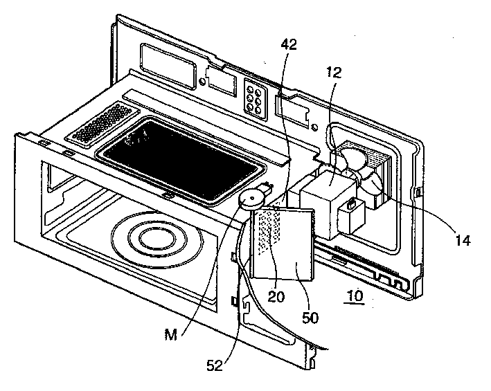
[0017] The air flow guide device for microwave ovens of the present invention will be further described in detail in conjunction with the accompanying drawings and specific embodiments: figure 2 Here we can see the air flow guiding device according to the invention. As shown in the figure, the electric control room 10 is provided with a magnetron 12 for generating microwaves, and a blower fan 14 for generating airflow to dissipate heat from the magnetron.

[0018] The side wall 42 of the electric control room 10 is provided with a heating room inlet 20 connected with the heating room and formed by many ventilation holes. The air flow generated in the blower fan 14 will cool the magnetron 12 and transformer etc. while passing them.

[0019] The air flow cooling the aforementioned components will then flow into the heating chamber through the heating chamber inlet 20 located in the side wall 42 .

[0020] Next, let's take a look at the structure of opening and closing the hea...


PUM


Abstract

The device for leading airflows comprises the magnetron, the transformer, the blowing fan, the entrance of the heating room in the electric control chamber as well as the plate type switching board and the actuating motor for rotating the switching board. The switching board opens or closes the heating room caused by rotating the one end setup at round the sidewall of the electric control chamber. The rotating center of the switching board positioned at the entrance of the heating room is at the end of the board far away from the blowing fan M. the rotating center is setup along the top and bottom direction. The switching board controls air passing through the entrance entering into inside the heating room. Comparing with prior art, the invented leading device is simpler. Thus, it reduces the production cost and the production efficiency.

Description

technical field [0001] The invention relates to the field of microwave ovens. Background technique [0002] A microwave oven is a device that provides microwaves to a heating chamber containing food and uses the microwaves to heat the food. An electric control room is arranged on the side of the heating room of the microwave oven. The electric control room is a place where electrical components that can generate microwaves are installed, such as magnetrons that can generate microwaves, transformers and capacitors that pressurize the magnetrons, etc. are installed inside. [0003] This electrical component will work together with the microwave oven and will generate heat as it works. Magnetrons and transformers will generate heat as they are driven, and if these heat-generating magnetrons and transformers are not dissipated in time, it will be detrimental to the magnetrons and transformers. Such as figure 1 As shown, the magnetron 12 arranged inside the electric control r...

Claims


Application Information

Patent Timeline
IPC IPC(8): F24C7/02F24C15/00
Inventor 朴满基
Owner LG ELECTRONICS (TIANJIN) APPLIANCES CO LTD
Why Eureka
Try Eureka