Resistance measuring circuit and detection, control and alarm apparatus comprising said circuit

A technology for measuring resistance and circuits, applied in resistance measurement circuits, alarm devices, control, and detection fields, can solve problems such as complex controlled current sources and complex structures of controlled current sources.

Inactive Publication Date: 2003-11-12
朱筱杰
View PDF1 Cites 33 Cited by
  • Summary
  • Abstract
  • Description
  • Claims
  • Application Information

AI Technical Summary

Problems solved by technology

[0003] In order to overcome the relatively complicated structure of the controlled current source in the above circuit, the present invention provides a circuit that can measure resistance with a similar principle while avoiding the use of a complicated controlled current source

Method used


Image

  • Resistance measuring circuit and detection, control and alarm apparatus comprising said circuit
  • Resistance measuring circuit and detection, control and alarm apparatus comprising said circuit
  • Resistance measuring circuit and detection, control and alarm apparatus comprising said circuit

Examples


Embodiment Construction

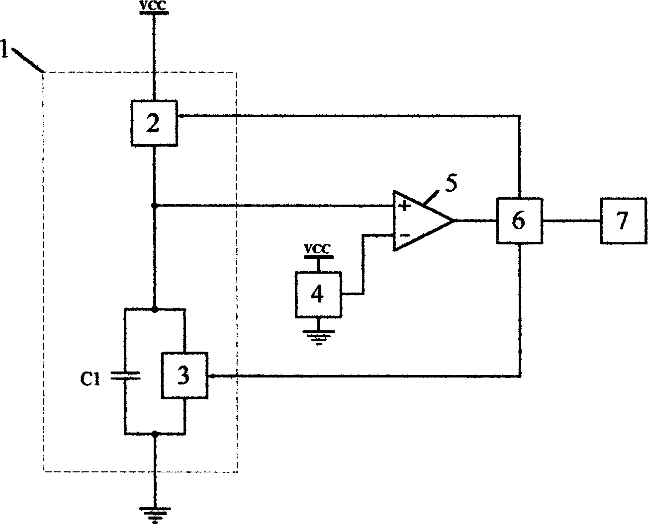
[0088] Figure 11 It is a circuit schematic diagram of Embodiment 1 according to the present invention. This embodiment shows the case where the charging module is a constant current source connected in series with an electronic switch, and the discharging module is a resistor. like Figure 11 , in this embodiment: the charging module is controlled by the charging switch [K 2 ] and the charging constant current source [I 2 ] connected in series, the discharge module consists of the resistance to be measured [R X ], the rest is the same as the basic schematic ( figure 1 )same. In this circuit, the charge counter counts the value N C It is actually the number of cycles in which the switch is turned on, the discharge counter count value N F is actually the total number of cycles N of the measurement period.

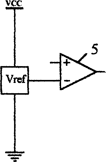
[0089] R X =(N / N C )×(V ref / I 2 ), when the reference voltage module is the reference voltage source (such as figure 2 )

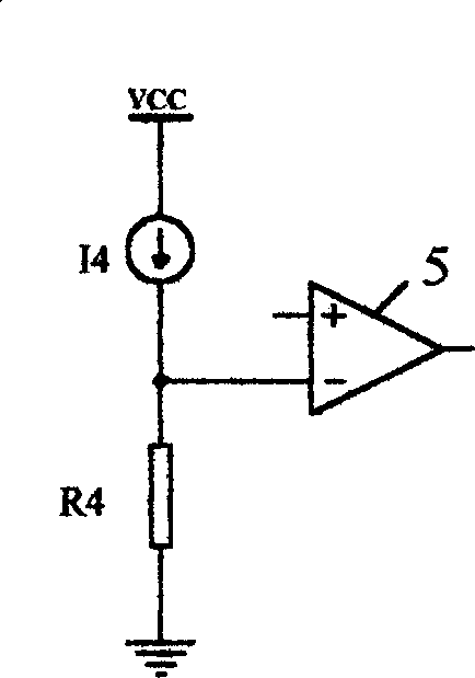
[0090] R X =(N / N C )×(I 4 / I 2 ...


PUM


Abstract

The circuit utilized for measuring resistances by using pulse modulation technique comprises the capacitance C1, the charging circuit, the discharging circuit, the comparator, the controller and the pulse-processing module etc. and the output of the comparator controls On/Off of the charging circuit and the discharging circuit. The resistance value can be calculated out from the number of the charging and the discharging period. The method is easy to be realized by using single chip with comparator build in, providing the measuring function of multi-channel, multi-range and high accuracy. Combining with thermistor, hygristor and photoresistor, the invented circuit can constitute the measuring, controlling and alarming devices based on temperature, humidity and light intensity.

Description

Technical field [0001] The invention relates to a circuit for measuring resistance, especially a resistance measuring circuit with linear characteristics, and a detection, control and alarm device including the circuit. Background technique [0002] The most basic method of measuring resistance is based on Ohm's law, that is, measuring the voltage across the resistance and the current flowing through the resistance, and calculating the quotient of the voltage and the current. Although this method is widely used, it also has its limitations. The patent document CN 1242522A discloses the invention patent application "Device for Automatically Measuring Resistance" (application number 99111480.9) of Philips, which provides a method, which uses a controlled current source to supply power to the resistance, and uses a comparator to compare the resistance voltage with the resistance voltage. The reference voltage is compared, and the comparison result drives an up and down counter...

Claims


Application Information

Patent Timeline
Patent Type & Authority Applications(China)
IPC IPC(8): G01R27/14
Inventor 朱筱杰
Owner 朱筱杰
Why Eureka
Try Eureka