
Video frequency electronystagmograph instrument and automatic generation of video frequency electronystagmograph

A technology of electroseismograph and electronystagmogram, which is applied in the fields of instruments, electronic digital data processing, and special data processing applications. Eliminate skin and electrode preparation, accurate and reliable parameter calculation, and high clinical diagnostic value

Inactive Publication Date: 2003-11-19
翁天祥
View PDF0 Cites 9 Cited by
  • Summary
  • Abstract
  • Description
  • Claims
  • Application Information

AI Technical Summary

Problems solved by technology

[0003] In the prior art, the electronystagmogram is recorded by guiding the weak corneal and retinal potential difference through epidermal electrodes to indirectly observe the eye movement displacement parameters. One of its inherent defects is that the signal-to-noise ratio is similar, and the effective signal is captured by the same frequency range. Therefore, the acquisition of electronystagmus requires a complex and high-precision signal amplification and adjustment circuit, and the clinical application effect is not ideal; second, due to the influence of the polarization potential of the skin electrode, the baseline drift of the nystagmus wave makes the Effective signals are difficult to identify; thirdly, the potential difference between cornea and retina is affected by many internal and external factors, such as arousal state, retinal blood supply and indoor light and shade, etc., making nystagmus calibration extremely complicated and difficult, and the reliability of the collected signals is also affected Fourth, the electronystagmogram cannot observe the rotation component of nystagmus, an important clinical indicator; fifth, the electronystagmogram recording in a dark room cannot provide doctors with the opportunity to observe nystagmus in real time
In conclusion, the existing electronystagmographic recording methods are complex, time-consuming and labor-intensive, and not effective enough

Method used


Image

  • Video frequency electronystagmograph instrument and automatic generation of video frequency electronystagmograph
  • Video frequency electronystagmograph instrument and automatic generation of video frequency electronystagmograph
  • Video frequency electronystagmograph instrument and automatic generation of video frequency electronystagmograph

Examples


Embodiment Construction

[0049] The present invention will be further described in detail below in conjunction with the accompanying drawings.

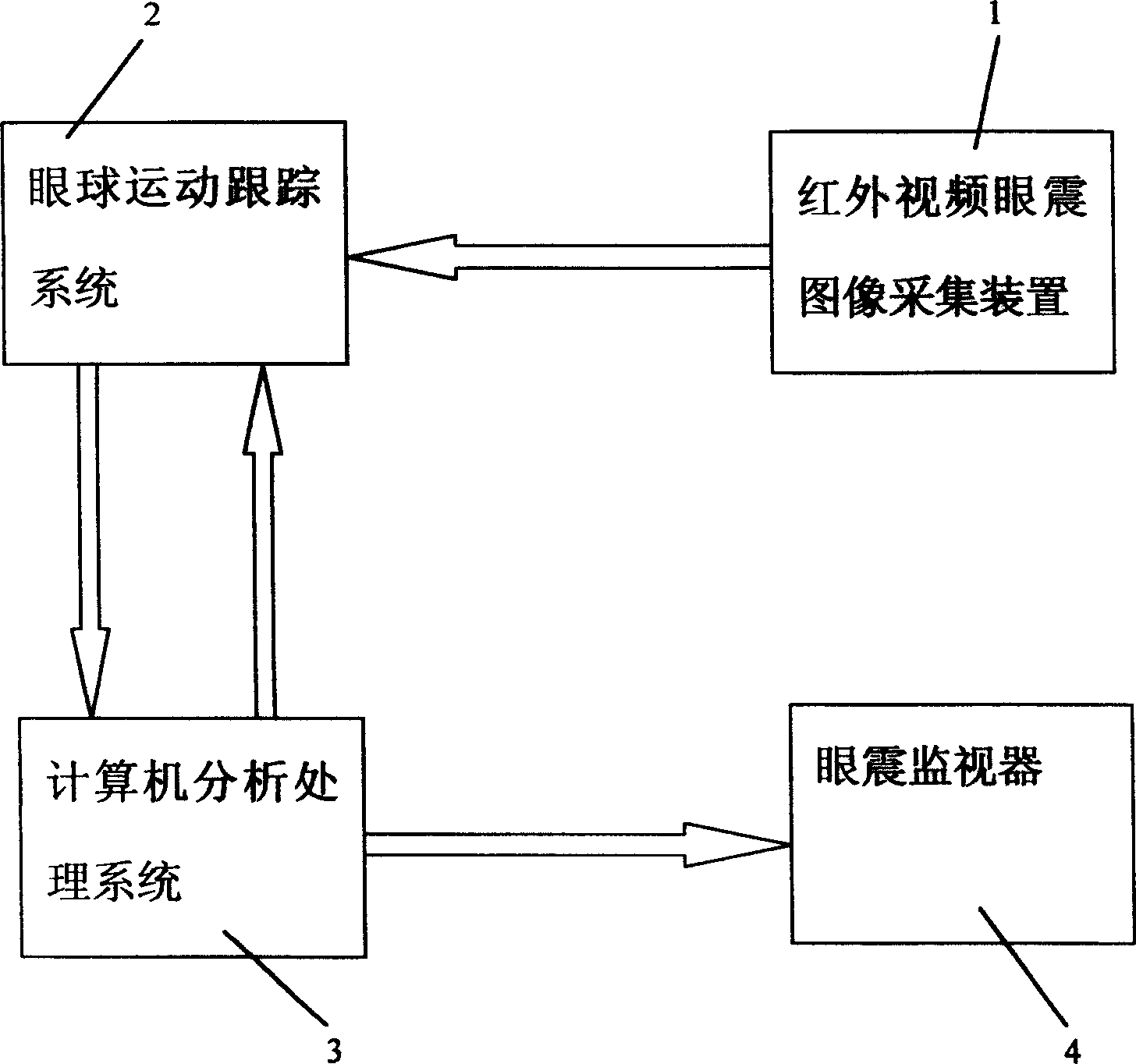
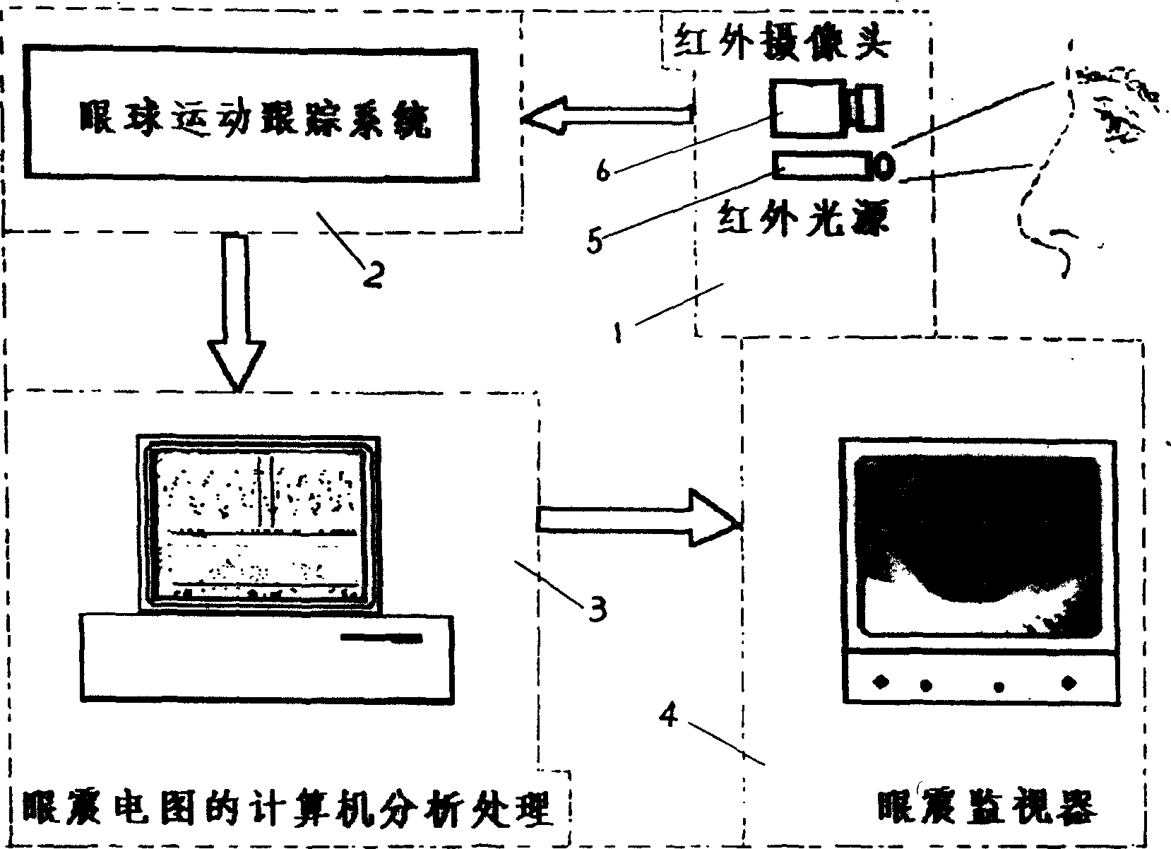
[0050] Such as figure 1 As shown, the video electronystagmogram of the present invention includes an infrared video nystagmus image acquisition device 1, an eye movement tracking system 2, a computer analysis and processing system 3 and a nystagmus monitor 4, and its connection relationship and signal transmission mode are as follows: The infrared video nystagmus image acquisition device 1 is connected to the eye movement tracking system 2 with a video signal, and the eye movement tracking system 2 is electrically connected to the computer analysis and processing system 3, and the computer analysis and processing system 3 uses a video signal Connected to the nystagmus monitor 4. figure 2 It shows the situation that the infrared video nystagmus image acquisition device 1 is composed of an infrared camera 6 with an infrared light source 5 .

[0051] The work...


PUM


Abstract

The electronystagmograph consists of infrared video nystagmus image collection device, eyeball motion tracing system, computer analysis processing system and nystagmus monitor, of which the said infrared video nystagmus image collection device is connected in video signal connection with the eyeball motion tracing system which is connected in electric connection with the computer analysis processing system, and the computer analysis processing system is connected in video signal connection with the said nystagmus monitor. The present invention provides also an automatic generation method for video electronystagmogram which can effectively storten clinical detecting time by real-time recording and analysing of physiological parameter for nystagmus at vertical parallel are rotary directions.

Description

technical field [0001] The invention relates to the field of medical equipment for ear neurology and vestibular function inspection, in particular to a video electronystagmogram and an automatic generation method of the video electronystagmogram. Background technique [0002] Electronystagmograph (Electronystagmograph, ENG) is currently a routine item for clinical detection of nystagmus, and is widely used in otolaryngology, neurology and ophthalmology. Electronystagmography, like other bioelectricity (ECG, EEG, EMG, etc.) records, is an important means of clinical disease diagnosis and efficacy evaluation. Through the examination and analysis of electronystagmography, doctors can more accurately judge the functional status and pathological process of the human vestibular balance function system and eye movement system, and can also assist in positioning diagnosis. [0003] In the prior art, the electronystagmogram is recorded by guiding the weak corneal and retinal potenti...

Claims


Application Information

Patent Timeline
IPC IPC(8): G06F19/00
Inventor 翁天祥
Owner 翁天祥
Learn More