Pneumatic tire

A technology of pneumatic tires and tires, which is applied to the reinforcement layer of pneumatic tires, tire parts, wheels, etc., and can solve the problems of increasing the wear speed and abnormal wear of the end part of the tire surface

Inactive Publication Date: 2003-11-26
BRIDGESTONE CORP
View PDF1 Cites 5 Cited by
  • Summary
  • Abstract
  • Description
  • Claims
  • Application Information

AI Technical Summary

Problems solved by technology

[0004] When the outer surface of the tread portion is deformed into the above-mentioned convex shape, there is a problem that the force in the forward direction (drive side) near the equatorial plane of the tire and the force in the rearward direction (brake side) near the end of the tread Acts on the outer surface of the rotating tread portion, which increases the wear rate of the end portion of the tread depending on the size (difference in the length of the outer circumference), resulting in abnormal wear

Method used


Image

  • Pneumatic tire
  • Pneumatic tire
  • Pneumatic tire

Examples


Embodiment

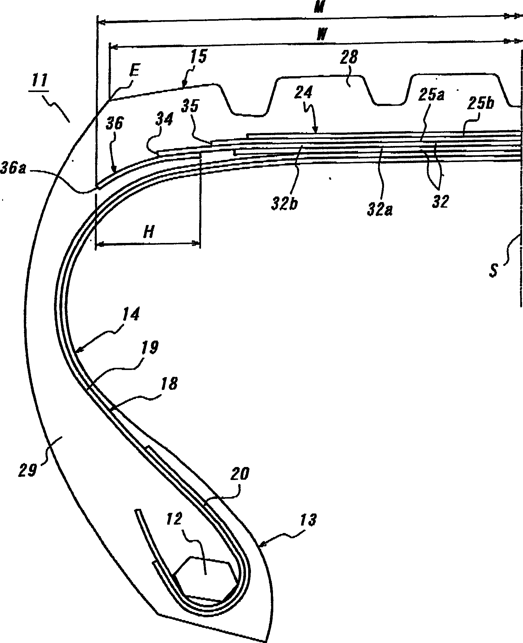
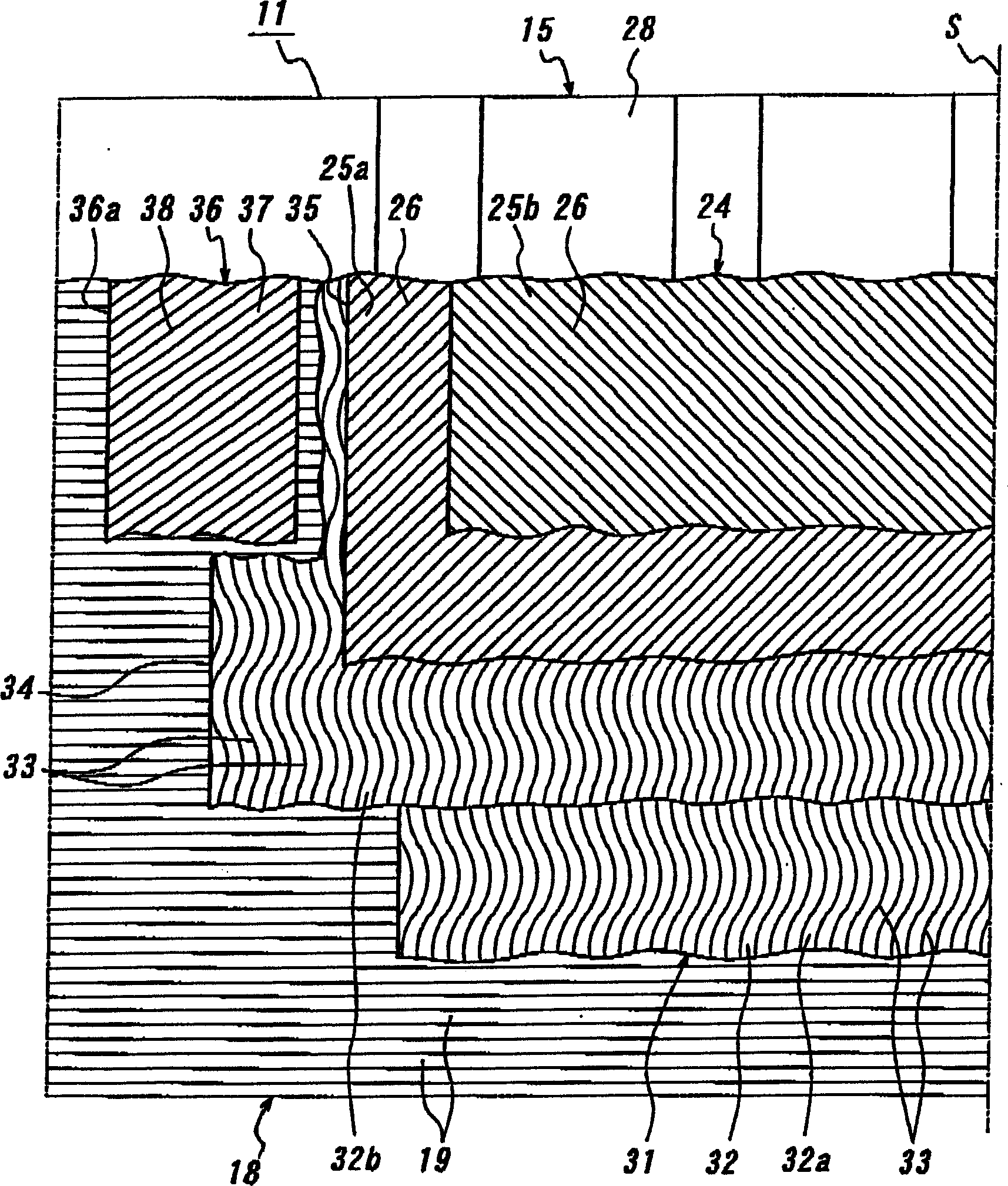
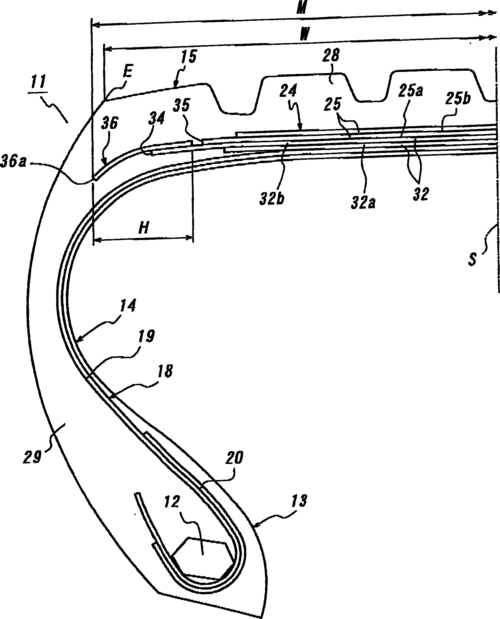
[0055] In order to verify the effect of the present invention, a test was carried out on 31 tires with a size of 435 / 45R22.5 and an axial distance W from the equatorial plane S to the tread end E of 185 mm. Among these tires, a conventional tire has Figure 4 The belt construction shown, except that there is no separate auxiliary belt ply; a control tire has the same belt construction as the conventional tire except that one of the belt plies is the widest. On the other hand, the tires in Examples 1 to 29 had Figure 1-9 Belt construction for the indicated belt layers, belts for the reinforcement layer of dimensions indicated in Table 1, and separate auxiliary belt layers.

[0056] Each test tire was then fitted to a 14.00 x 22.5 rim, internally inflated to a pressure of 900 kPa, and mounted to the drive wheels of a large bus with a 2-D wheel system. Afterwards, the tire ran 10,000km on the expressway at a speed of 80km / h under the condition of a load of 49.0kN. After running...


PUM


Abstract

In a pneumatic tire comprising a carcass, a belt arranged at the outside of the carcass in a radial direction and comprised of at least two belt layers, at least one belt reinforcing layer arranged so as to overlap with the belt and extend over a widthwise outer end thereof, and a tread rubber arranged at the outside of the belt in the radial direction, a pair of split auxiliary belt layers are arranged so as to overlap at least with both widthwise outer end portions of a widest-width belt reinforcing layer and reinforcing elements having an inclination angle different from that of reinforcing elements in the belt reinforcing layer are embedded in the split auxiliary belt layer for decreasing the wearing rate at the tread end portion of the tire to effectively control irregular wear.

Description

technical field [0001] The present invention relates to pneumatic tires capable of controlling rapid wear at the end of the tread. Background technique [0002] Pneumatic tires generally contain a belt composed of at least two interlaced belt layers, and interlaced reinforcing units are embedded in the equatorial belt layer of the tire. Japanese Patent JP-A-2000-203215 discloses a pneumatic tire having at least one belt reinforcing layer wider than the belt layer, wherein most of the reinforcing units are embedded therein so as to extend in the direction of the outer circumference during wavy or zigzag bending , and further control the separation failure at the lateral outer edge end of the belt layer to improve the durability of the belt. [0003] However, the outer surface of the tread portion of the pneumatic tire comprising the tires described in the above publications is generally made into a single arch structure with a single curvature radius or a plurality of arch s...

Claims


Application Information

Patent Timeline
Patent Type & Authority Applications(China)
IPC IPC(8): B60C9/20B60C9/22B60C9/28
CPCB60C9/28B60C9/22B60C9/20Y10T152/10765Y10T152/10792Y10T152/10801
Inventor 清水明祯
Owner BRIDGESTONE CORP
Why Eureka
Try Eureka