Run flat tire
A technology for run flat tires and tires, which is applied to the reinforcement layer of pneumatic tires, tire parts, tire tread/tread pattern, etc., and can solve the problems of increasing tire weight, etc.
- Summary
- Abstract
- Description
- Claims
- Application Information
AI Technical Summary
Problems solved by technology
Method used
Image
Examples
no. 1 approach
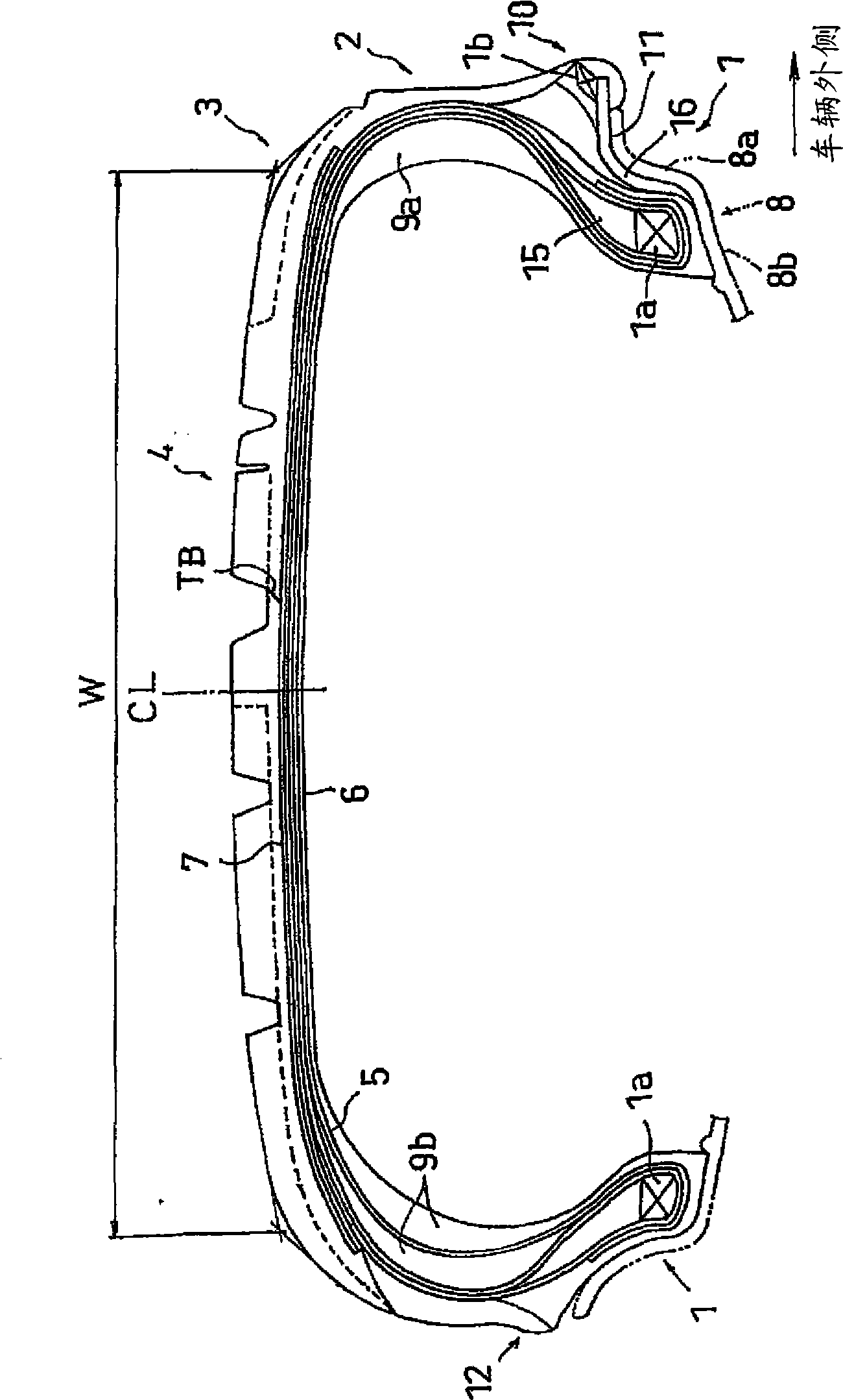
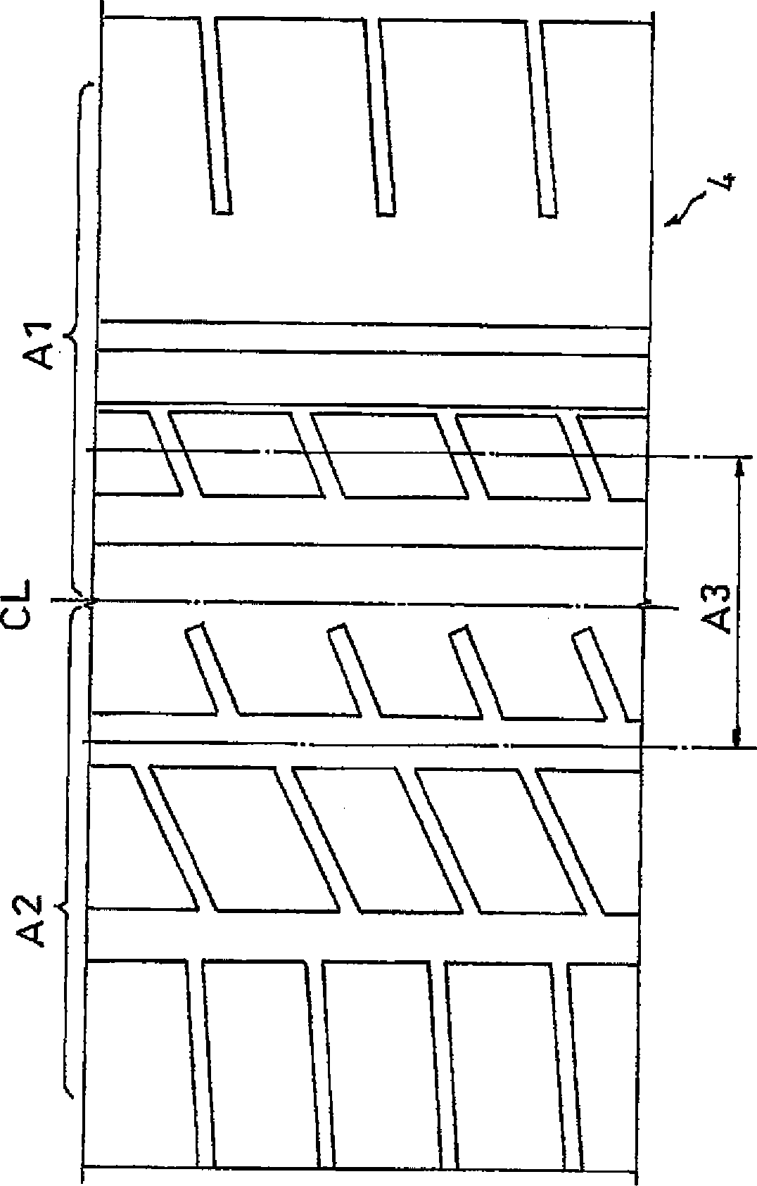
[0055] figure 1 It is a tire meridian sectional view showing the run flat tire according to the first embodiment of the present invention when mounted on a standard rim. figure 2 is showing figure 1 A developed view of an example of a tread pattern of a mid-runner flat tire.
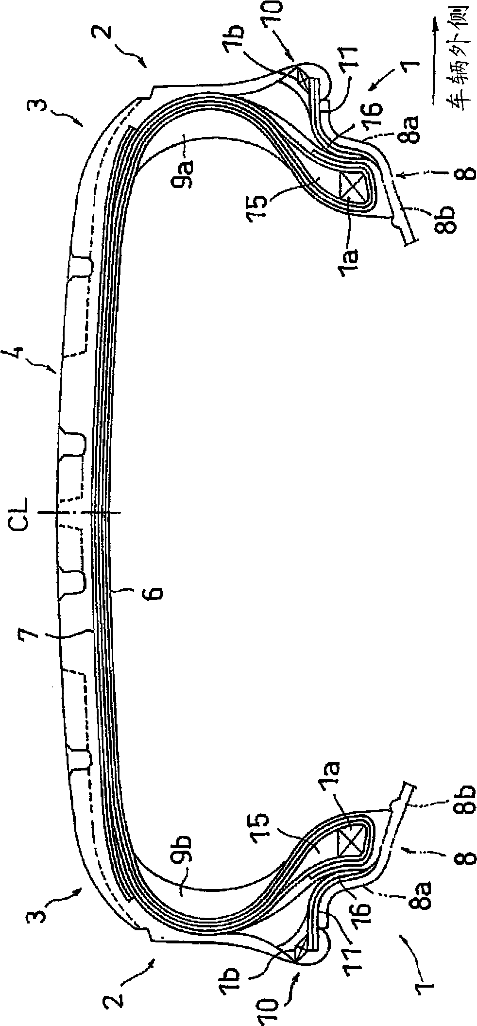
[0056] Such as figure 1 As shown, the run flat tire of the present invention has: a pair of bead portions 1; sidewall portions 2 extending from the bead portions 1 to the radially outer side of each tire; and the outer peripheries of the sidewall portions 2 connected by shoulder portions 3 The tread portion 4 between the side ends.
[0057] The bead portion 1 is provided with: a bead 1 a (corresponding to the first bead) in which a bead wire bundle formed of, for example, steel wire forms a ring shape in the tire circumferential direction; and a bead filler 15 . The end portion of the carcass 5 is rolled back and stopped by the bead 1a, whereby the tire is firmly fitted and attached to the rim 8 in ...
Embodiment 1-1~1-2
[0092] Experimental tires were manufactured as follows: figure 1 The structure shown (but only one kind of tread rubber is used) and as figure 2 The pattern shown has the bending stiffness of the belt layer and the rubber hardness (PAD hardness) of the reinforcing rubber layers on both sides shown in Table 1, and furthermore, the maximum difference in thickness of the reinforcing rubber layers on both sides is 0mm, and the vehicle outer side Void ratio / vehicle inner void ratio=1, tread rubber hardness is 68°, and size is 245 / 40R18. The evaluation results are shown in Table 1 together.
Embodiment 2-1~2-5
[0101] Experimental tires were manufactured as follows: figure 1 The structure shown (but only one kind of tread rubber is used) and as figure 2 The pattern shown in Table 2 has the bending stiffness of the belt layer, the rubber hardness (PAD hardness) of the reinforcing rubber layer on both sides, the tread rubber hardness, the void ratio of the vehicle outer side / the void ratio of the vehicle inner side, and further , so that the difference between the maximum thickness of the reinforced rubber layer on both sides is 0mm, and the size is 245 / 40R18. The evaluation results are shown in Table 2 together.
PUM
| Property | Measurement | Unit |
|---|---|---|
| Rubber hardness | aaaaa | aaaaa |
| Rubber hardness | aaaaa | aaaaa |
| Rubber hardness | aaaaa | aaaaa |
Abstract
Description
Claims
Application Information
 - R&D
- Intellectual Property
- Life Sciences
- Materials
- Tech Scout
- Unparalleled Data Quality
- Higher Quality Content
- 60% Fewer Hallucinations
Browse by: Latest US Patents, China's latest patents, Technical Efficacy Thesaurus, Application Domain, Technology Topic, Popular Technical Reports.
© 2025 PatSnap. All rights reserved.Legal|Privacy policy|Modern Slavery Act Transparency Statement|Sitemap|About US| Contact US: help@patsnap.com


