Drilling bit structure for enlarging hole

A technology of drill bit and drill bit sleeve, which is applied in the direction of drill bit, earth-moving drilling, drilling equipment, etc., can solve the problems of not being able to be pulled out, hindering the reverse rotation of the extended drill bit, etc.

Inactive Publication Date: 2003-12-10
林秉德
View PDF0 Cites 1 Cited by
  • Summary
  • Abstract
  • Description
  • Claims
  • Application Information

AI Technical Summary

Problems solved by technology

[0009] However, in said prior patents, foreign matter such as soil and stone particles can get between the bit sleeve and the extension bit which are rotated at a deep underground position for drilling operation, thus hindering the reverse rotation of the extension bit, and therefore It also prevents concentric alignment between the extension bit and the bit sle

Method used


Image

  • Drilling bit structure for enlarging hole
  • Drilling bit structure for enlarging hole
  • Drilling bit structure for enlarging hole

Examples


Embodiment Construction

[0016] Reference will now be made in detail to the preferred embodiments of the invention, examples of which are shown in the accompanying drawings.

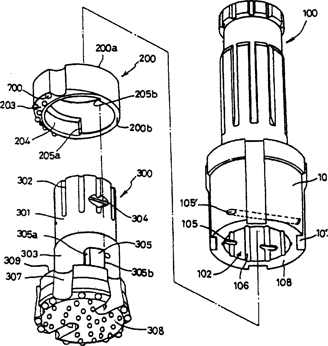
[0017] As shown, the drill sleeve 100 has a body 101 with a pilot connection opening 102 eccentrically formed therein. The body 101 is also provided with vertical pin slots 106 and horizontal pin holes 105, 105' at regular intervals in its inner periphery.

[0018] The pilot bit 300 is connected in the pilot connection opening 102 by inserting the locking pin 500 followed by the rotation stop pin 400, while the expansion bit 200 is connected between the pilot bit 300 and the bit holder 100, thereby basically constituting a hammer drill.

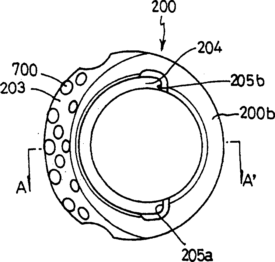
[0019] The expanding drill bit 200 is a half-stroke driving body, which is used to substantially expand a hole through the bit housing 100 and the pilot bit 300 . The expansion drill 200 performs a hole reaming operation as it rotates eccentrically to the guide drill 300 .

[0020] The extens...


PUM


Abstract

The present invention relates to a stereo object-tracking method and system. The method for adaptively controlling a stereo object-tracking system that is composed of a first image input device and a second input device comprises the steps of detecting a target object included within at least two input images, which the first image input device picks up sequentially, through a background matching of the two input images; separating the target object by the use of a target projection mask from the two input images; generating a reference image including the target object; extracting first locational coordinates by comparing at least one target image, which the second image input device picks up, with the reference image; and controlling the second image input device with the first locational coordinates.

Description

technical field [0001] The present invention relates to a drill bit structure for reaming, which is capable of drilling holes beyond the diameter of a hammer drill bit in groundwater development or in building or public works works. The present invention is an improvement on Korean Patent No. 309297 previously filed by the inventor. Background technique [0002] According to the creation structure of the expansion bit of the hole, the expansion bit is formed eccentrically to the center line of the drill sleeve and is rotatable together with the drill sleeve. In said prior patent, the centerlines of the members are also formed eccentrically. [0003] In said prior patent, a fitting step for turning the extension bit is formed in the bottom surface of the bit casing, and a fitting step is also formed in the top surface of the extension bit so that the bit casing and the extension bit can pass between the steps The bite and be rotated together. [0004] However, in said prio...

Claims


Application Information

Patent Timeline
IPC IPC(8): E21B10/26H04N7/18
CPCG01S3/7865G06T7/2086H04N7/181H04N5/23212G06T2207/10021H04N5/232G06T2207/10012G06T7/285H04N23/60H04N23/67H04N7/18
Inventor 林秉德
Owner 林秉德
Why Eureka
Try Eureka