Long-stator iron core electric performance testing device

A technology for electrical performance and testing devices, applied in the field of measuring instruments, to reduce debugging time, ensure normal operation, and reduce laying costs

Inactive Publication Date: 2003-12-10
TONGJI UNIV +1
View PDF0 Cites 7 Cited by
  • Summary
  • Abstract
  • Description
  • Claims
  • Application Information

AI Technical Summary

Problems solved by technology

[0003] The purpose of the invention is to solve the technical problems about the electrical performance test of the long stator iron core

Method used


Image

  • Long-stator iron core electric performance testing device
  • Long-stator iron core electric performance testing device
  • Long-stator iron core electric performance testing device

Examples


Embodiment Construction

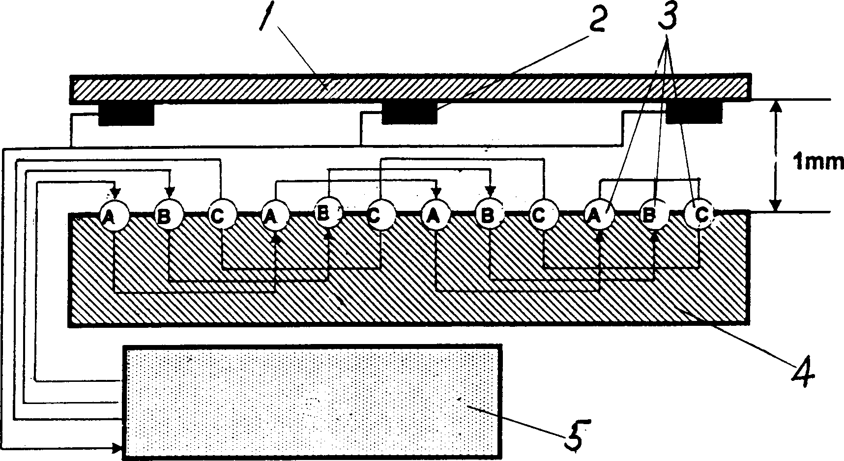
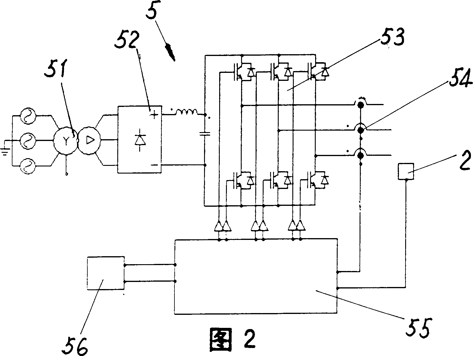
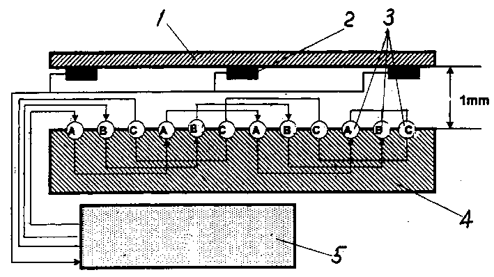
[0013] see figure 1 . The present invention is provided with a magnetic induction block 1 , a magnetic flux sensor 2 , a three-phase armature winding 3 and a measurement control system 5 . The magnetic induction block 1 is a whole ferromagnetic material; or it is composed of laminated sheets of ferromagnetic material, such as silicon steel sheets. The magnetic flux sensor 2 is a magnetic flux sensor utilizing the Hall effect, it is arranged on the magnetic induction block 1, and its output end is electrically connected with the measurement control system 5 by wires. One end of the three-phase (A, B, C) armature winding 3 is short-circuited, and the other end is electrically connected to the measurement control system 5 respectively. The measurement and control system 5 (see Figure 2) includes a transformer 51, a rectifier 52, an inverter 53 and a three-phase current closed-loop control system 55, which is a current with an effective value of 0-300 amperes and a frequency of ...


PUM


Abstract

The testing equipment of electric performance of long-stator iron core has a magnetic induction block, a fluxgate sensor positioned on the above-mentioned magnetic induction block, a three-phase armature winding can be inlaid in the slot of long-stator iron core to be tested and a measurement control system which is respectively electrically connected with the above-mentioned fluxgate sensor and three-phase armature winding and contains input transformer, rectifier, inverter and three-phase current cloosed-loop control system.

Description

Technical field: [0001] The invention relates to a measuring instrument, in particular to a long stator iron core electrical property testing device. Background technique: [0002] High-speed maglev trains are moving from theoretical research to practical use, and the driving power currently used is a long-stator linear synchronous motor. The stator winding segments of this long stator linear synchronous motor are arranged along the guide rails on the left and right sides, and each long stator winding segment contains several long stator core blocks arranged in sequence, and each long stator core block is provided with There are 3×n (n is a natural number greater than 2) slots, and the three-phase stator windings are embedded in the slots. When working, input variable-frequency DC current to the above-mentioned three-phase stator windings to generate running power under the condition of maintaining a constant distance (that is, the magnetic levitation air gap) with the fiel...

Claims


Application Information

Patent Timeline
Patent Type & Authority Applications(China)
IPC IPC(8): G01R33/00G01R33/12
Inventor 李耀华吴祥明黄靖宇韦榕徐善纲
Owner TONGJI UNIV
Why Eureka
Try Eureka