Channel disc connector for open-end spinning device

A technology of open-end spinning and splicer, which is applied in spinning machine, open-end spinning machine, continuous winding spinning machine, etc., can solve the problem of insufficient magnetic fixation of yarn guide nozzle, high price, complicated manufacturing, etc. problems, to achieve reliable connection, reduce manufacturing costs, and improve stability.

A technology of open-end spinning and splicer, which is applied in spinning machine, open-end spinning machine, continuous winding spinning machine, etc., can solve the problem of insufficient magnetic fixation of yarn guide nozzle, high price, complicated manufacturing, etc. problems, to achieve reliable connection, reduce manufacturing costs, and improve stability.

CN1461833AInactive Publication Date: 2003-12-17SAURER GERMANY GMBH & CO KG

Image

  • Channel disc connector for open-end spinning device
  • Channel disc connector for open-end spinning device
  • Channel disc connector for open-end spinning device

Examples


Embodiment Construction

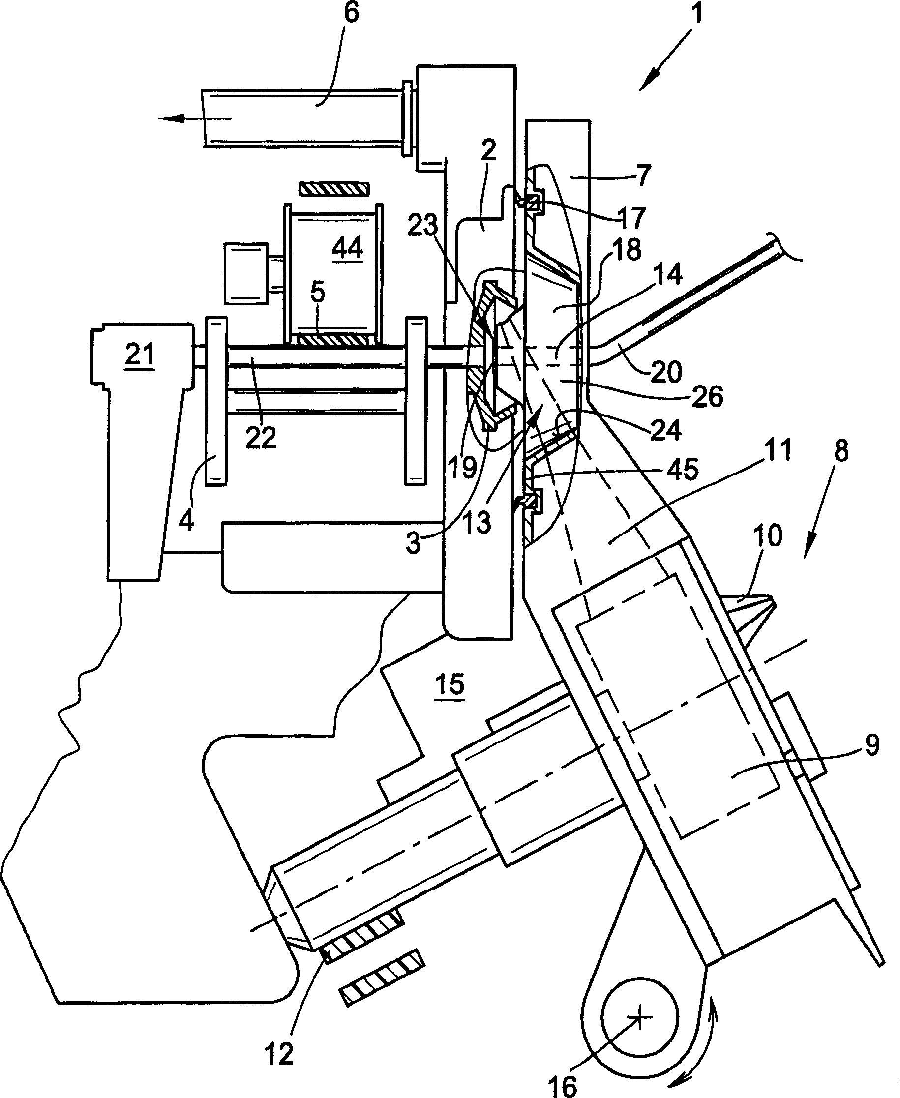
[0036] figure 1 The rotor spinning device 1 shown in the figure has a known rotor housing 2 in which a rotor 3 rotates at high speed during spinning production. The rotor 3 is supported with its rotor shaft 22 in the bearing wedge of the washer bearing 4 and is axially fixed by an axial bearing 21 , for example a permanent magnet.

[0037] The rotor 3 is usually driven by a tangential drive belt 5 which leans against the rotor shaft 22 by means of a support roller 44 .

[0038] The rotor housing 2, which is open to the front, is connected to a vacuum source (not shown) via a suction line 6 and is closed at the front by a so-called fiber channel disk 45 during spinning production.

[0039] The fiber channel disk 45 is mounted on a housing 7 which is rotatably mounted around the axis of rotation 16 and bears against the end face of the rotor housing 2 with a lip sealing element 17 .

[0040] Furthermore, a sliver feeding and opening mechanism 8 is integrated in the housing 7 ,...


PUM


Abstract

An open-end spinning assembly has a main body with an aperture for a channel plate adapter. The main body has a central passage with a thread extractor jet and a ceramic jet orifice (19). The jet orifice is esp. located directly within the central passage (14) within the main body (26).

Description

technical field [0001] The invention relates to a tunnel disc adapter according to the preamble of claim 1 . Background technique [0002] For example, such a channel disc adapter described in DE 43 34 485 A1 is basically composed of a base body that is preferably designed as a circle, with a backside, designed as a conical bearing surface and a tube The mouth piece is composed of the nozzle piece, which protrudes into the rotor during spinning production, and its size should be consistent with the specified rotor diameter or a diameter range. [0003] The nozzle region of a so-called fiber guide channel is machined into this nozzle part of the channel disc adapter. In addition, there is a centrally arranged thread guide nozzle. [0004] That is to say, such channel disc adapters have a central channel opening, on the inlet side of which an exchangeable yarn guide nozzle is fastened, and on the outlet side a so-called yarn guide tube engages in the central channel opening....

Claims


Application Information

Patent Timeline
17 Dec 2003
Publication
CN1461833A
IPC
D01H4/40
CPC
D01H4/40
Inventors
E·松塔; R·丹纳