
Multifunctional fuel gas stove

A gas cooker, multi-functional technology, applied in heating fuel, household appliances, household stove/stove, etc., can solve the problems of inconvenient size adjustment, inability to ensure success, inconvenient use and waste, etc.

Inactive Publication Date: 2003-12-17
陈振农
View PDF3 Cites 13 Cited by
  • Summary
  • Abstract
  • Description
  • Claims
  • Application Information

AI Technical Summary

Problems solved by technology

[0002] The currently used gas cooker relies on controlling the opening degree of the on-off valve to change the gas source pressure of the quantitative eruption hole, and then changes the size of the fire by controlling the flow rate of the gas source, which is obviously inconvenient during use: ( 1) It is inconvenient to adjust the size. The gas cooker with the existing structure is non-gradual in the regulation of the size of the fire. The effective range of the real and obvious change in the size of the control range of 90 degrees is only about 20 degrees, and the size is not easy to grasp.
(2) It is inconvenient to turn on the ignition. Turning on the ignition cannot ensure 100% success. Once the ignition is unsuccessful, not only will there be air leakage, which is harmful to the health and safety of the user, but also the valve must be turned off and then turned on again; in addition, the cooker with flameout protection After the ignition is successfully turned on, it still needs to be pressed for a few seconds, which brings inconvenience to the operation
(3) Frequently open and close the switch button. In the process of continuous cooking, on the one hand, for the sake of saving gas, and on the other hand, for safety, especially between two dishes, the usual practice is to either turn the gas source Turn it off to the minimum, or simply turn off the gas source, and then turn it on again, which not only wastes gas, but also brings inconvenience to operation
(4) There is no timing device, which brings inconvenience to those who need to cook regularly, such as cooking soup, decocting medicine, etc., especially once the user temporarily leaves the stove in use for some reason, it is very prone to accidents
(5) The applicable gas source is single. Due to the regional differences in the gas sources used, once the user changes the gas source due to relocation or other reasons, he may either refit the stove or discard it, causing inconvenience and waste in use.

Method used


Image

  • Multifunctional fuel gas stove
  • Multifunctional fuel gas stove
  • Multifunctional fuel gas stove

Examples


Embodiment Construction

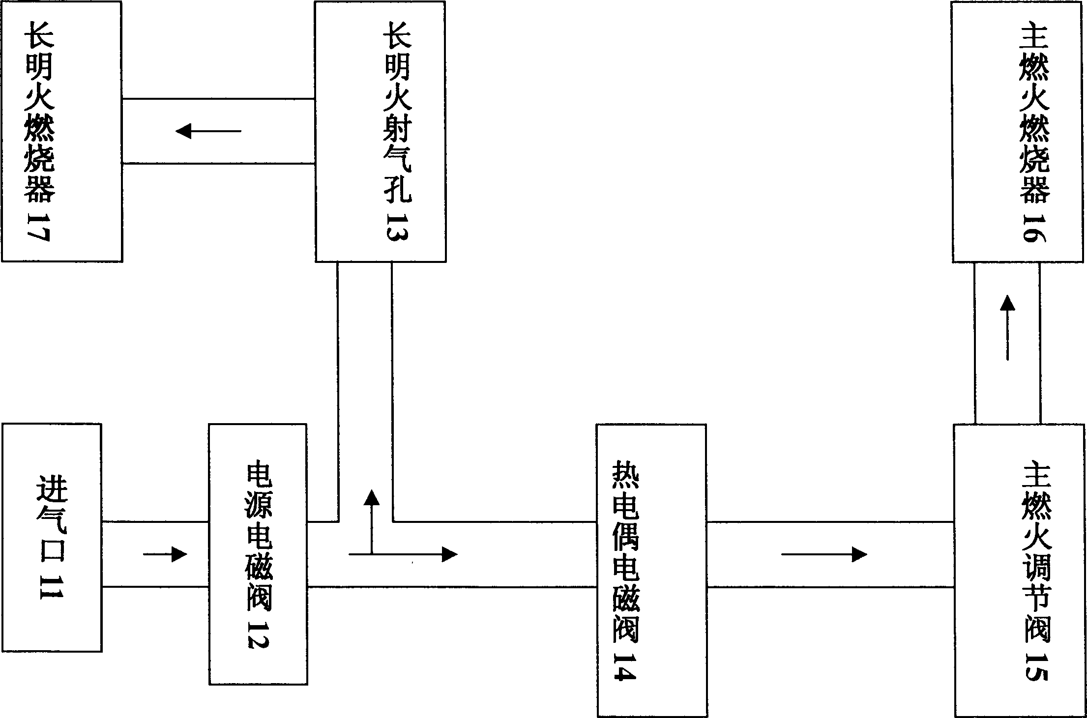
[0018] figure 1 It is the principle block diagram of the gas circuit of the whole cooker of the present invention, wherein the structure of the main ignition regulating valve 15 can be found in the application number 02111025.5 Figure 5 shown. It can be seen from the figure that the power solenoid valve 12 is arranged on the channel of the gas cooker air inlet 11, and the long open flame jet hole 13 is in the shape of a circular vent hole, and is arranged on the first branch road at the rear end of the power solenoid valve 12, quantitatively controlled The size of the constant flame fire, the thermocouple solenoid valve 14 is arranged on the second branch of the power supply solenoid valve 12 rear end;

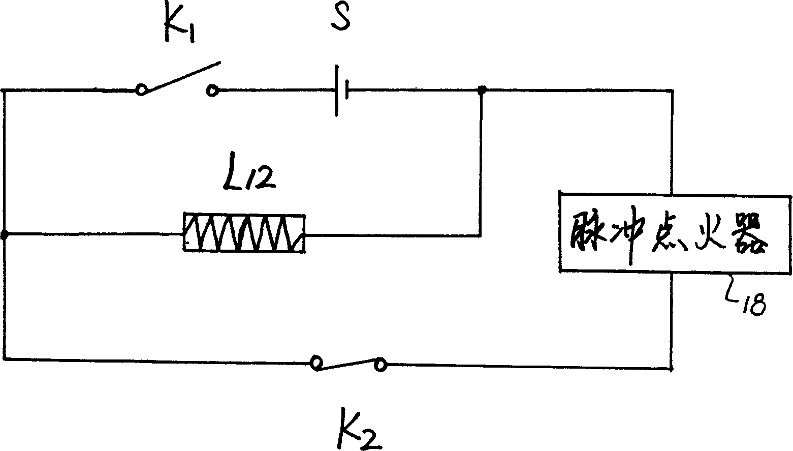
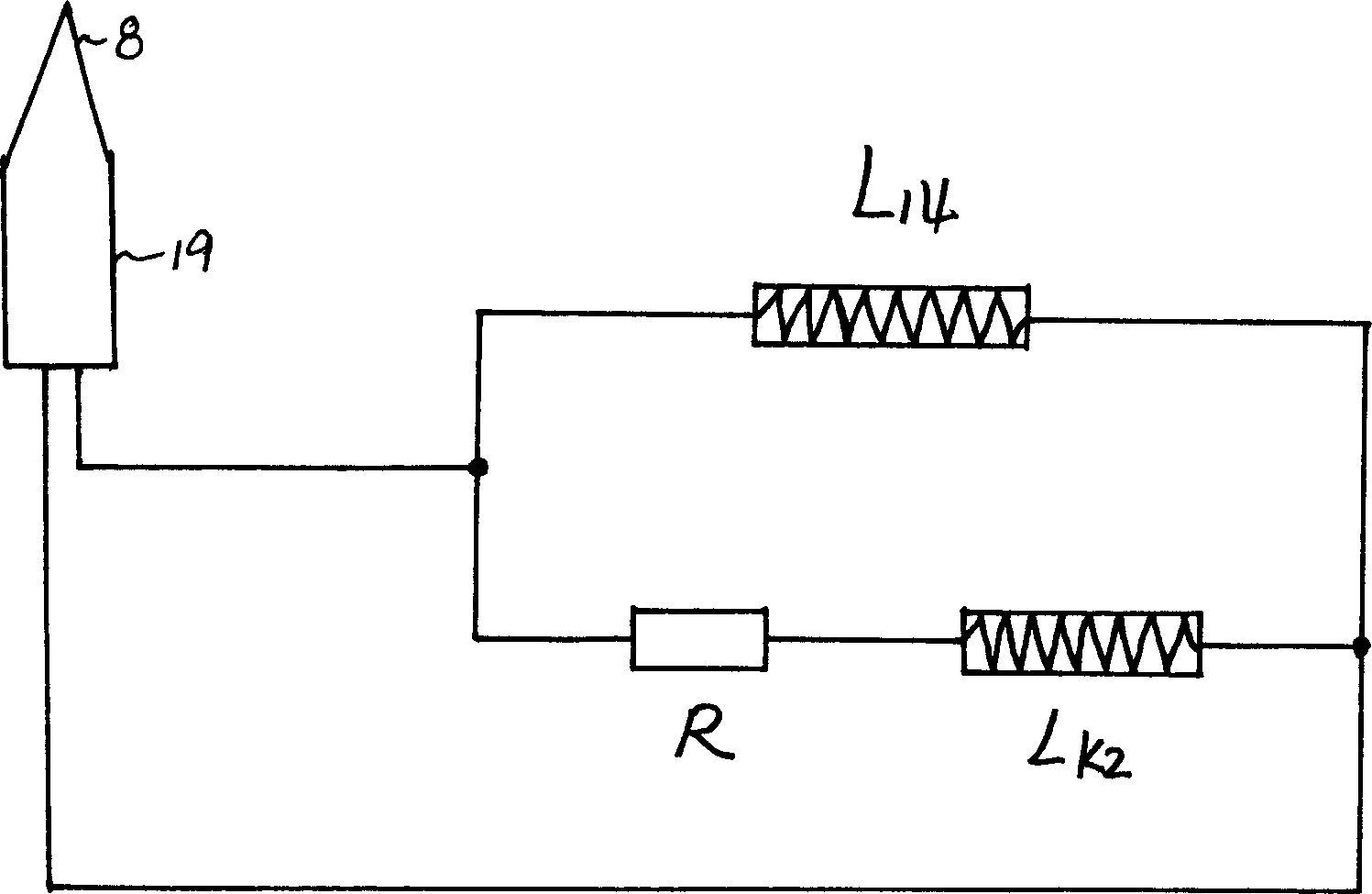
[0019] figure 2 with image 3 It is the circuit diagram of the control gas path and pulse ignition. figure 2 The first circuit composed of the medium power supply S-linkage switch K1-the inductance coil L12 of the power solenoid valve is the control circuit for controll...


PUM


Abstract

A multifunctional gas stove is composed of electromagnetic valve for power supply arranged in gas inlet channel, gas jet hole for normal fire flame, thermocouple electromagnetic valve with thermal sensor near the burner of normal fire flame, primary flame regulating valve, and pulse igniter with a normal closed reed relay, which plays such role that after ignition is finished the igniter can not be used and when the flame is accidently extinguished, the igniter can be automatically used.

Description

technical field [0001] The utility model relates to a gas cooker, in particular to a gas cooker which is convenient for large adjustment and integrates multiple functions. technical background [0002] Currently used gas cookers rely on controlling the opening degree of the switch valve to change the gas source pressure of the quantitative eruption hole, and then change the size of the fire by controlling the flow rate of the gas source, which is obviously inconvenient during use: ( 1) It is inconvenient to adjust the size. The gas stove with the existing structure is non-progressive in the regulation of the size of the fire. The effective range of really changing the size within the control range of 90 degrees is only about 20 degrees, and the size is not easy to grasp. (2) It is inconvenient to turn on the ignition. Turning on the ignition cannot ensure 100% success. Once the ignition is unsuccessful, not only will there be air leakage, which is harmful to the health and s...

Claims


Application Information

Patent Timeline
Patent Type & Authority Applications(China)
IPC IPC(8): F24C3/12
Inventor 陈振农
Owner 陈振农
Learn More