

Safety early warning method and system for super highway
A technology of expressway and early warning system, applied in the traffic control system of road vehicles, traffic control system, alarm, etc., can solve the problems of false alarm, high investment cost, difficult implementation, etc., and achieve easy realization, cost economy, easy The effect of implementation
- Summary
- Abstract
- Description
- Claims
- Application Information
AI Technical Summary
Problems solved by technology
Method used
Image

Examples
Embodiment 1
[0024] Embodiment one 1, overall condition
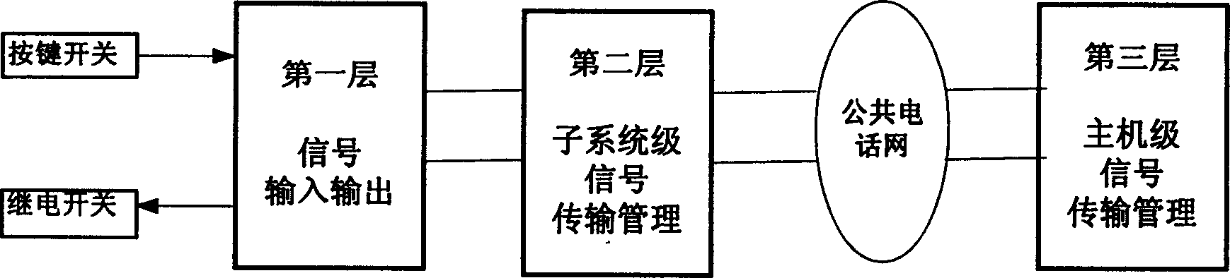
[0025] The logical structural relationship of the expressway safety instant early warning system of the present embodiment is as follows: figure 1 As shown, the system is composed of a signal input and output device on the first floor, a subsystem signal transmission management device on the second floor, and a host signal transmission management device on the third floor. The first and second layers are physically integrated into a microcomputer subsystem, the first layer is used as an expansion module of the second layer, and the first, second and third layers are interconnected through the public telephone network. Geographically, the alarm devices are regularly distributed. Due to the existing public telephone network, the system adopts a master-slave hierarchical structure. The whole system is composed of multiple subsystems, and a subsystem is used for unified control at intervals. Unified organization and management by a sin...
Embodiment 2
[0045] The overall scheme of this implementation (see Figure 7 ) is basically the same as Embodiment 1, and the logic structure diagram of this general scheme is similar to the logic structure diagram of Embodiment 1, it can not pass through the public telephone network between the first, second and third levels, but by twin glue lines. even.
[0046] The subsystem of this implementation is basically the same as that of Embodiment 1, the difference is that differential transmission is adopted, data communication is carried out in the way of transmission relay, and the receiving end directly decodes to control the relay switch.
[0047] The internal structure of the implementation example system is as follows: Figure 8 shown. The subsystem consists of a general controller, control circuit nodes, indicating circuit nodes, and repeaters. The general controller, the control circuit node and the repeater are connected in series, and connected in parallel with the indication ci...
Embodiment 3
[0052] This embodiment ( Figure 11 ) is different from the master-slave structure of embodiment one and embodiment two overall scheme logical structure diagrams, it is a kind of open-loop distributed parallel structure, each microcomputer subsystem has no master-slave relationship, between each microcomputer subsystem wire interconnection ( Figure 12 ).
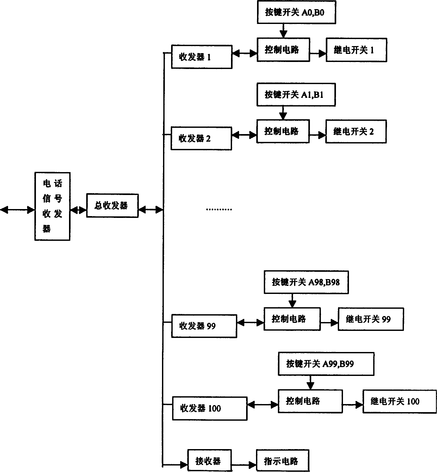
[0053] Will figure 2 Delete the public telephone network and the telephone signal transceiver in the subsystem, which is the subsystem structure of this embodiment. The subsystem structure, working principle and working process of this embodiment can refer to figure 2 To illustrate.
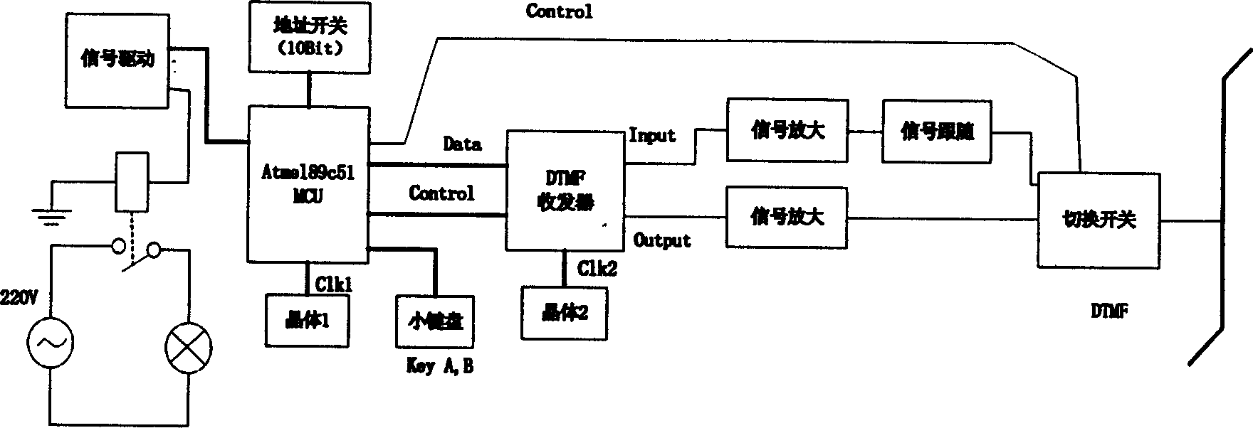
[0054] In this figure, each control node in the subsystem is composed of transceiver, control circuit, key switch and relay switch. The transceiver is composed of corresponding DTMF signal generating and receiving chips. The key switch corresponds to switch A and B. The control circuit uses a single-chip microcomputer chip to complete...
PUM
 Abstract
Description
Claims
Application Information