Laser beam machine

A laser processing machine and laser beam technology, applied in laser welding equipment, metal processing equipment, manufacturing tools, etc., can solve the problems of inadvertently cutting materials, lowering nesting efficiency, and difficulty in high-speed processing, and achieve the elimination of inadvertently cutting materials. , Reduce the production manpower, and realize the effect of high speed

Inactive Publication Date: 2004-01-14
YAMAZAKI MAZAK KK
View PDF0 Cites 10 Cited by
  • Summary
  • Abstract
  • Description
  • Claims
  • Application Information

AI Technical Summary

Problems solved by technology

[0007] However, in the above-mentioned processing method, since the nozzle needs to be moved along the movement path formed by the above-mentioned three straight lines → circular arc → straight line in each processing of the sharp angle, there is a need to feed the nozzle with a specified feed rate. The time it takes for the speed to rotate around the moving path hinders the speed-up of processing
In particular, when there are many sharp corners that must be processed, for example, when multiple parts with sharp corners to be cut are arranged on the workpiece 70 (nesting), or in the case of parts to be cut In the case of multiple sharp corners, the processing speed decreases due to the increase in the number of rotations around, and it is more difficult to achieve high-speed processing
[0008] In addition, in the creation of the machining program, it is necessary to insert the loop R program LRP composed of three blocks corresponding to the straight line → circular arc → straight line in each machining block of the acute angle, so it takes a lot of effort to insert, Especially in the case of the above-mentioned sharp corners that need to be processed, there is a disadvantage that more manpower is required
Moreover, corresponding to the number of sharp angles, there is a disadvantage that the program storage capacity for the loop R program LRP is further required
In addition, since the track of the loop R inserted into the corner is large, there is a disadvantage that the material is cut off in vain, and the nesting efficiency is reduced.

Method used


Image

  • Laser beam machine
  • Laser beam machine
  • Laser beam machine

Examples


Embodiment Construction

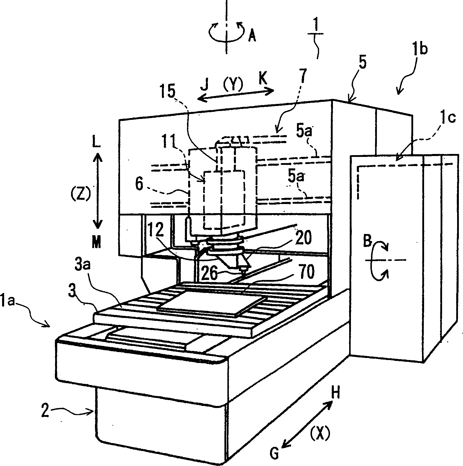
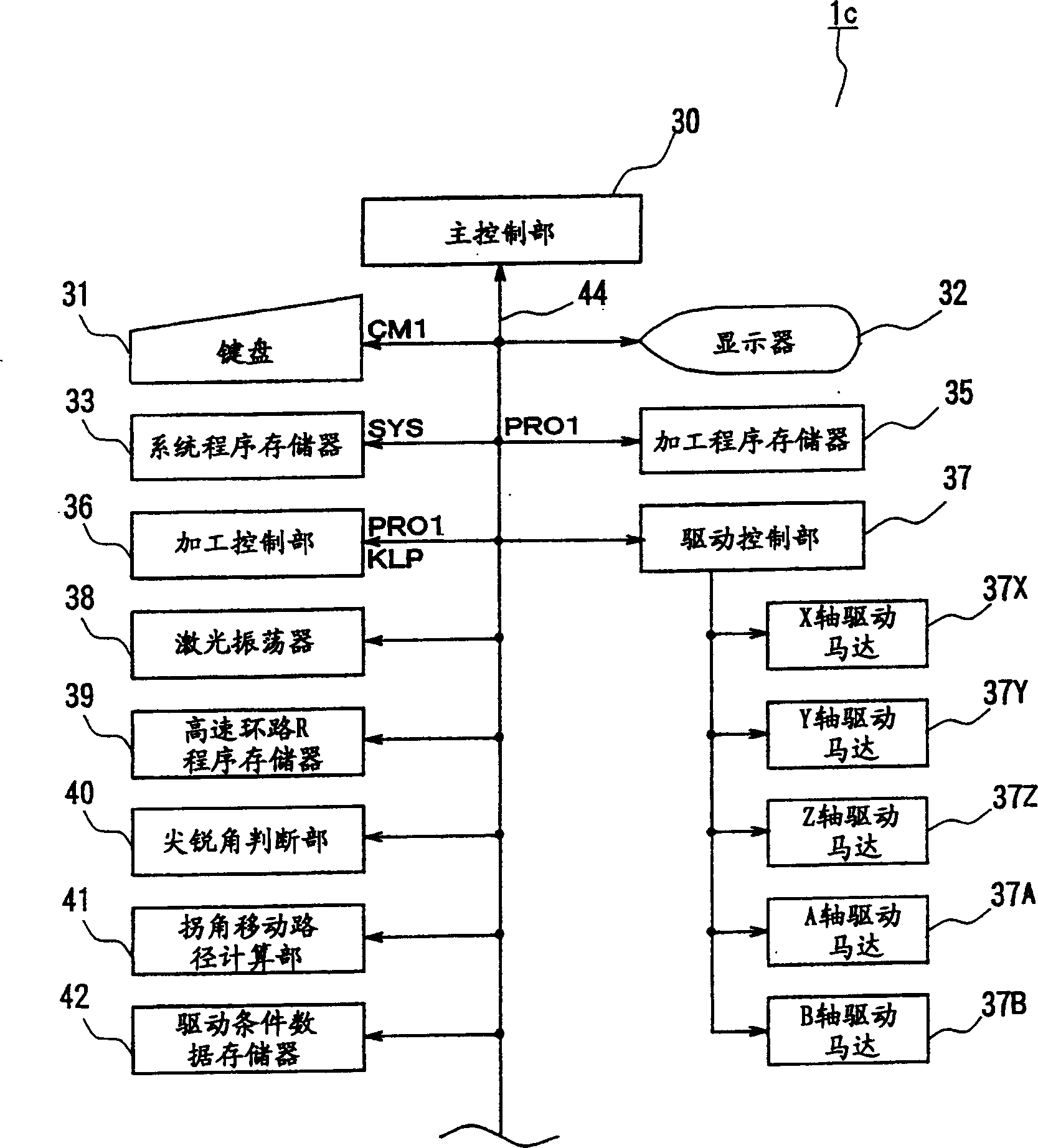
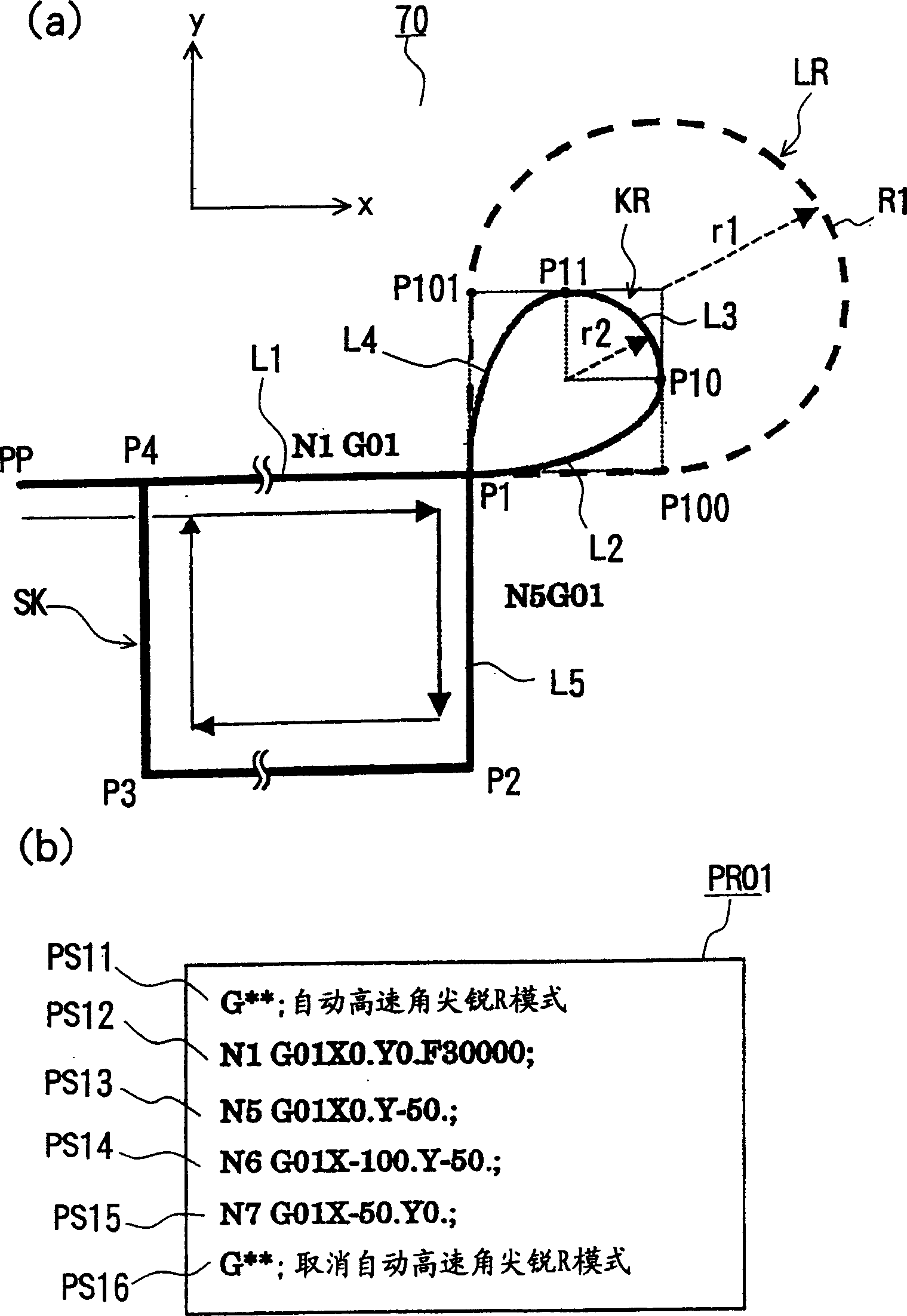
[0025] figure 1 It is an overall perspective view of a laser processing machine applicable to the present invention, figure 2 yes figure 1 A block diagram of the control device in the laser processing machine, image 3 It is a diagram showing an example of the cutting form near the corner part of the workpiece, (a) is a diagram of a high-speed loop R of the moving path, (b) is a diagram of an example of a machining program, Figure 4 is a flowchart showing the contents of the automatically generated program JSP which is a subroutine of the high-speed loop R program, Figure 5 It is an explanatory diagram of the execution of the high-speed loop R program, (a) is an explanatory diagram of the calculation of the moving path, (b) is a moving diagram of the nozzle along the high-speed loop R, Figure 6 is a graph of each cutting path based on the corner angle.

[0026] Laser processing machine 1 applicable to the present invention, such as figure 1 As shown, for example, a...


PUM


Abstract

A sharp corner judgment means judges as to whether a corner of cut shape in a workpiece is a sharp corner is not on the basis of a machining program. When the corner is regarded as the sharp corner, an additional locus producing means for producing sharp corner produces an additional locus for producing sharp corner when machining on the corner regarded as the sharp corner, and a sharp corner machining execution means executes machining on the corner on the basis of the produced additional locus for producing sharp corner. Then, the additional locus for producing sharp corner can be automatically produced for the sharp corner so as to execute machining.

Description

technical field [0001] The present invention relates to a laser processing machine capable of cutting a plate-shaped workpiece. Background technique [0002] Figure 7 It is a diagram showing an example of a state of cutting near a corner portion by a conventional machining method, (a) shows a loop R of a movement path, and (b) shows a part of an example of a machining program. [0003] In the past, when using a laser processing machine to cut a sharp angle formed by intersecting straight cutting paths, for example, such as Figure 7 As shown in (a), when the sharp angle formed by the intersection of the straight line cutting path L1 and L5 (solid line) is cut at the position P1 (x coordinate is 0, y coordinate is 0), along the same figure (a) After the cut-off path L1 is cut in the direction of the arrow, the cut-off path L5 is not cut off immediately, but along the loop R (LR) indicated by the dotted line in the same figure (a), according to the position P1, P100 (x coordi...

Claims


Application Information

Patent Timeline
Patent Type & Authority Applications(China)
IPC IPC(8): B23K26/00B23K26/38G05B19/416
CPCB23K26/0807B23K26/08B23K26/082
Inventor 山崎恒彦宫川直臣井上利彦饭领田晃
Owner YAMAZAKI MAZAK KK
Why Eureka
Try Eureka