Automatic variable saw bit devices

A saw blade, automatic technology, applied in sawing machine equipment, metal sawing equipment, metal processing equipment and other directions, can solve the problem of increasing the size of the mechanical mechanism of the fighting robot competition site

Inactive Publication Date: 2004-02-04
SHANGHAI JIAO TONG UNIV
View PDF0 Cites 7 Cited by
  • Summary
  • Abstract
  • Description
  • Claims
  • Application Information

AI Technical Summary

Problems solved by technology

Since the device completes the horizontal and vertical movements by mechanical devices such as lead screws, racks and pinions, the size of the mechanical mechanism of the combat robot competition field device is increased, and it is not suitable for the random and automatic change of the position of the combat robot obstacle (saw blade).

Method used


Image

  • Automatic variable saw bit devices
  • Automatic variable saw bit devices

Examples


Embodiment Construction

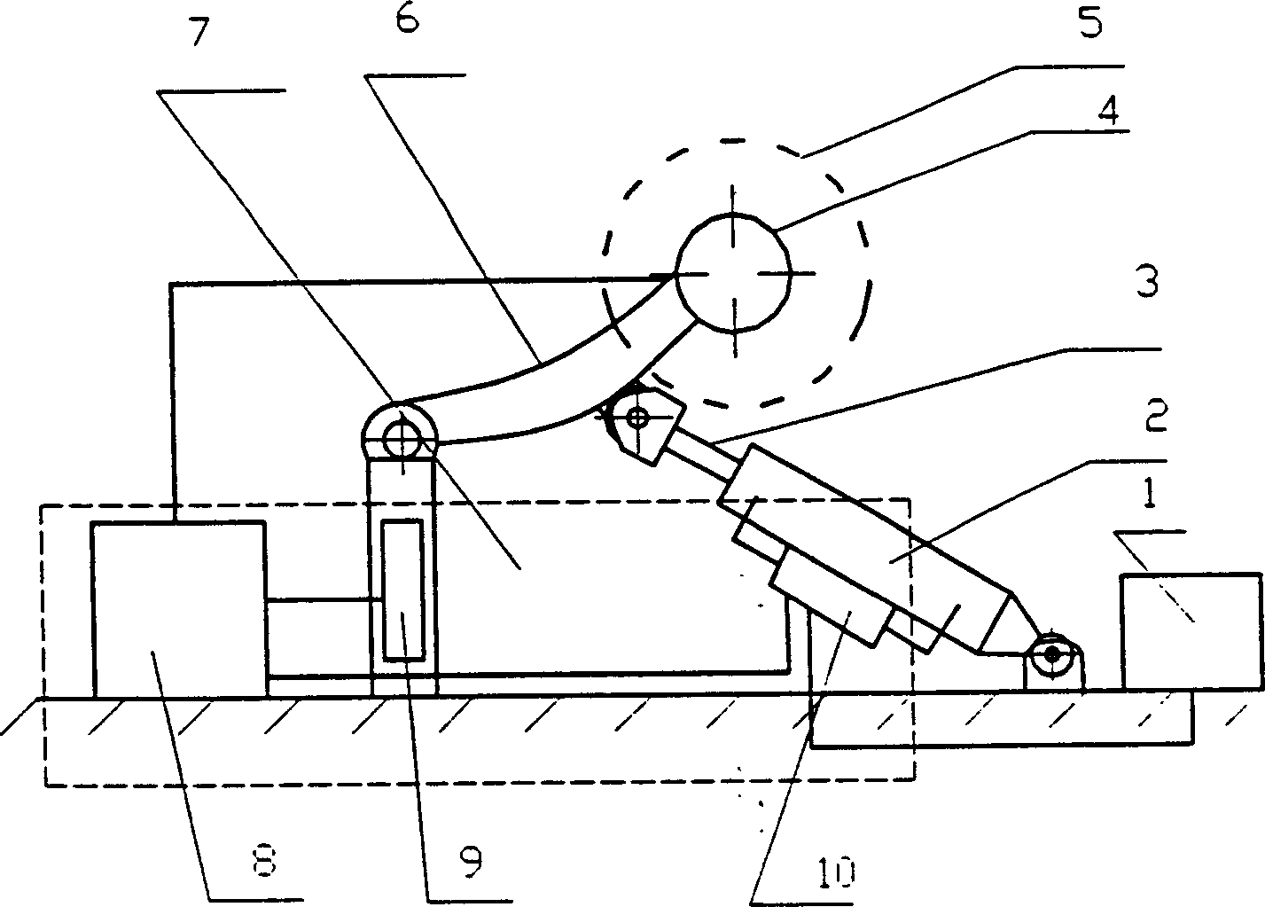
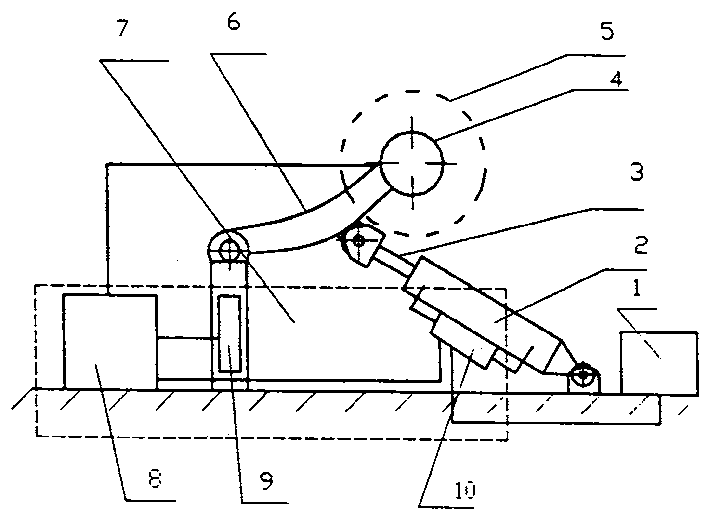
[0009] Such as figure 1 As shown, the present invention includes: a pneumatic control system 1, a cylinder 2, a piston connecting rod 3, a motor 4, a saw blade 5, a rotating bracket 6, and an electrical control system 7, and its connection mode is: the pneumatic control system 1 is placed on the supporting surface , the cylinder 2 is connected with the pneumatic control system 1 by the air pipe, one end of the cylinder 2 is connected with the fixed bracket by a hinge, the piston connecting rod 3 is set in the cylinder, the piston connecting rod 3 and the rotating bracket 6 are connected by a hinge, and the motor 4 is fixed on the rotating bracket 6, rotate around the hinge on the fixed bracket together with the rotating bracket 6, the saw blade 5 is connected with the motor 4 shaft, and the solenoid valve 10 in the electric control system 7 is fixed on the cylinder. The electrical control system 7 includes: a control box 8, a limit switch 9, and a solenoid valve 10. The connec...


PUM


Abstract

An automatically changing saw blade unit used as the obstacle in robot fight game to destroy the robot is composed of pneumatic control system, cylinder, piston and its connecting rod, motor, saw blade, rotary supporter and electric control system with electromagnetic valve fixed to said cylinder.

Description

technical field [0001] The invention relates to a saw blade device, in particular to an automatic variable saw blade device, which belongs to the field of mechanical engineering. Background technique [0002] Most of the existing saw blade devices are fixed when the saw blade rotates rapidly, and the size of the mechanical device is relatively large, which cannot meet the requirements of random changes of obstacles (saw blades) on the fighting robot's site, cutting steel shells, fighting robots, etc. Require. It is found through literature search that Yu Cheng and others wrote an article "Design of Automatic Scrap Billet Cutting Machine" in "Metallurgical Equipment", No. 4, 1998, P19-20, which introduced a scrap steel billet automatic cutting machine. The machine travels to the cutting site through a trolley. When the cutting machine is cutting, the horizontal and vertical drive systems are driven by ordinary squirrel-cage motors, and the actuator is driven by a reducer, wh...

Claims


Application Information

Patent Timeline
Patent Type & Authority Applications(China)
IPC IPC(8): B23D47/10
Inventor 费燕琼钟礼东赵锡芳
Owner SHANGHAI JIAO TONG UNIV
Why Eureka
Try Eureka