Continuous production device of steel plastic composite pipe having holed steel skeleton surface coated with binder
A steel-plastic composite pipe, surface coating technology, applied to pipes, rigid pipes, pipes/pipe joints/pipe fittings, etc., can solve problems such as no connection strength, weak joints, and poor practical application effects
- Summary
- Abstract
- Description
- Claims
- Application Information
AI Technical Summary
Problems solved by technology
Method used
Image

Examples
Embodiment 1
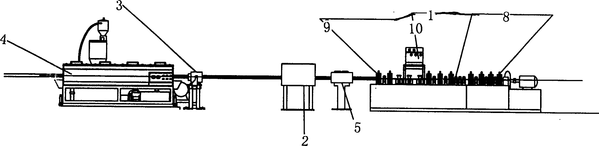
[0057] Figure 1 to Figure 5 , provides the figure of Embodiment 1 of the present invention. According to the composite pipe forming process, there are forming and sizing welding mechanism 1, adhesive coating mechanism 2, extrusion compounding mechanism 3, sizing and cooling forming mechanism 4, and heater 5 for skeleton and / or sticky powder skeleton.
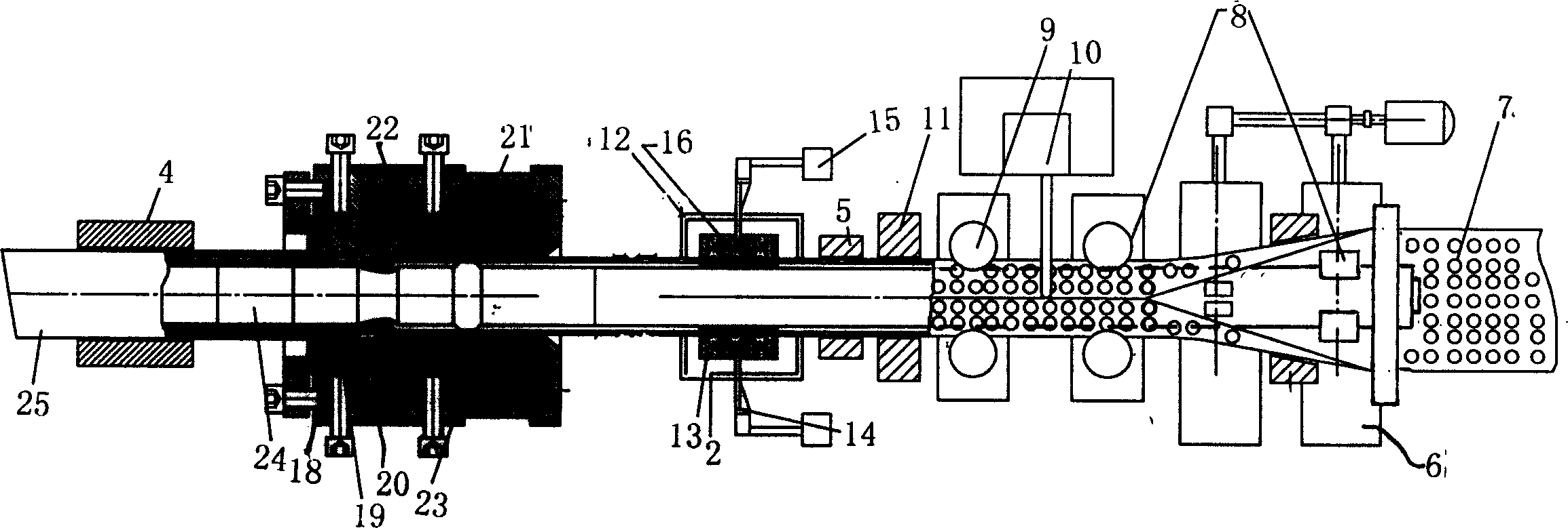
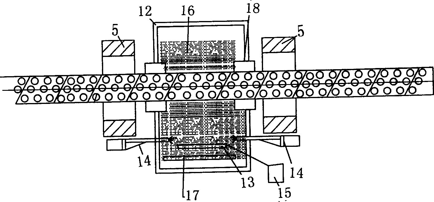
[0058] see figure 2 , the forming and sizing welding mechanism of the cylindrical steel frame is a frame 6, a former forming mechanism 8 that can make the steel plate 7 with holes longitudinally rolled into a cylindrical frame and is composed of multiple forming wheels mounted on the frame, A sizing mechanism 9 composed of multiple sets of fixed wheels, a welding motor 10 and a cylindrical skeleton sizing sleeve 11 that can further accurately shape and calibrate the formed cylindrical skeleton are formed. The powder recovery shield box 12 is arranged in the binder coating mechanism, the fluidized bed 13 positioned in the pow...
Embodiment 2
[0060] Figure 6 Figure 2 of Embodiment 2 of the present invention is given. Embodiment 2 is basically the same as Embodiment 1. The difference is that the front and rear of the adhesive coating mechanism are provided with cylindrical skeleton heaters 5 . The advantages of setting heaters separately can increase the thickness of the coating adhesive so that the coated adhesive can better melt and coat the skeleton, which can increase the preheating capacity of the skeleton and make it better in the die head of the extrusion composite mechanism. The polymer continuum is formed in the inner and outer layers of the skeleton and bonded or compounded with the binder and the skeleton more firmly.
Embodiment 3
[0062] Figure 7, Figure 8 A schematic structural diagram of Embodiment 3 of the present invention is given. In the present embodiment, there are steel wire helically wound cylindrical steel skeleton forming and sizing welding mechanism 26, steel wire skeleton using adhesive spraying mechanism 27, extruding composite mechanism 28 for extruding polymer, and sizing and cooling forming mechanism 29 for composite pipe. The forming and sizing welding mechanism 26 includes a frame 27, a radial pay-off frame 28 located at the front end of the frame, a mandrel 30 containing a cylindrical support electrode 29 mounted on the frame, and an empty sleeve on the mandrel driven by a motor to wind the wire. Rotary disk 31, the welding pad 32 that is driven by the motor to rotate on the mandrel. On the welding pad, the mandrel is the axis of symmetry and a pair of positive and negative poles are respectively connected to the three-phase power supply 33 on the position corresponding to the cond...
PUM
 Abstract
Description
Claims
Application Information
 - R&D
- Intellectual Property
- Life Sciences
- Materials
- Tech Scout
- Unparalleled Data Quality
- Higher Quality Content
- 60% Fewer Hallucinations
Browse by: Latest US Patents, China's latest patents, Technical Efficacy Thesaurus, Application Domain, Technology Topic, Popular Technical Reports.
© 2025 PatSnap. All rights reserved.Legal|Privacy policy|Modern Slavery Act Transparency Statement|Sitemap|About US| Contact US: help@patsnap.com