Electric compressor

A compression device and electric technology, applied in the direction of compressors, compressors, irreversible cycle compressors, etc., can solve the problems of increasing costs and achieve the effect of reducing costs

Inactive Publication Date: 2004-02-25
DENSO CORP
View PDF1 Cites 7 Cited by
  • Summary
  • Abstract
  • Description
  • Claims
  • Application Information

AI Technical Summary

Problems solved by technology

However, these approaches come with the added cost of

Method used


Image

  • Electric compressor
  • Electric compressor
  • Electric compressor

Examples


no. 1 example

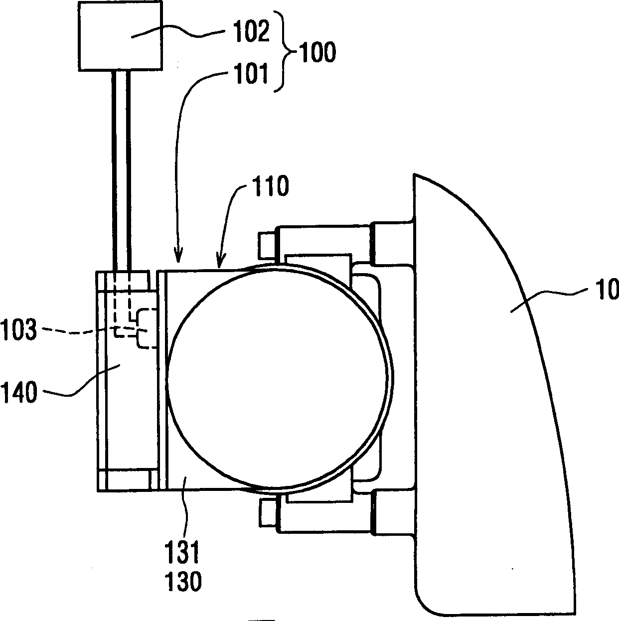
[0026] Refer to the following figure 1 Through 4 describe the electric compression device 100 of the first embodiment of the present invention. The electric compression device 100 is used in an on-vehicle refrigeration cycle device, and it is installed in the engine compartment, for example, fixed to the engine 10 . Such as figure 1 and 2 The electric compression device 100 shown includes an electric compressor 101 and a control unit 102 .

[0027] The electric compressor 101 has a motor part 110 , a compressor part 120 , a housing 130 and an inverter 140 . The casing 130 is an encapsulating casing composed of a motor casing 131 , a middle casing 132 and a rear casing 133 ; the casing accommodates the motor part 110 and the compressor part 120 . The inverter 140 is attached to an outer surface of the housing 130 .

[0028] The motor section 110 has a three-phase AC motor housed in a motor case 131 . The rotating shaft of the motor is connected to the compressor part 120 ...


PUM


Abstract

An electric compression device has a motor section and a compressor section contained in a housing, an inverter attached to the outer surface of the housing, and a temperature measurement device for measuring a temperature of the inverter. In a stopped state of a refrigeration cycle system, a control unit drives the motor section when the temperature of the inverter, measured by the temperature measurement device, exceeds a predetermined temperature.

Description

technical field [0001] The invention relates to an electric compression device, which can be used in vehicle-mounted refrigeration cycle equipment, such as air-conditioning systems. Background technique [0002] As a general electric compression device, Japanese Patent No. 3086819 discloses an electric compression device in which a case (casing) accommodates a compressor portion and a motor portion. The power semiconductor module (inverter) for driving the motor is mounted on the wall of the housing so as to face the low-voltage side inside the housing. [0003] Correspondingly, the low temperature and low pressure cool the power semiconductor modules prior to partial pressurization by the compressor. Then, since a dedicated heat sink, a blower, and the like become unnecessary, it is possible to reduce the cost and reduce the size of the drive circuit. [0004] However, when such an electric compression device is stopped, the refrigerant does not cool down the power semico...

Claims


Application Information

Patent Timeline
Patent Type & Authority Applications(China)
IPC IPC(8): F04D27/00B60H1/32F25B1/00F25B31/00
CPCF25B2700/21152F25B31/006F25B2700/2115F25B2600/021
Inventor 竹本刚穗满敏伸
Owner DENSO CORP
Why Eureka
Try Eureka