Transmission equipment and releasing arrangement

A technology of tripping device and transmission device, applied in the field of electric machinery, can solve the problems of design and use that have not been effectively solved, high-voltage circuit breaker operating power, and the influence of tripping sensitivity.

Inactive Publication Date: 2004-03-10
沈阳亚泰高压电力设备制造有限公司
View PDF0 Cites 6 Cited by
  • Summary
  • Abstract
  • Description
  • Claims
  • Application Information

AI Technical Summary

Problems solved by technology

[0003] The problem of the design and use of the transmission device in the spring operating mechanism of the high-power (above 8000J) high-voltage circuit breaker has not been effectively resolved.
This makes the structure of the trip mechanism more complicated, and the response time of the trip is prolonged (generally above 30ms), which adversely affects the sensitivity of the trip
[0005] In summar

Method used


Image

  • Transmission equipment and releasing arrangement
  • Transmission equipment and releasing arrangement
  • Transmission equipment and releasing arrangement

Examples


Embodiment Construction

[0031] The present invention will be described in further detail below in conjunction with the embodiments and accompanying drawings.

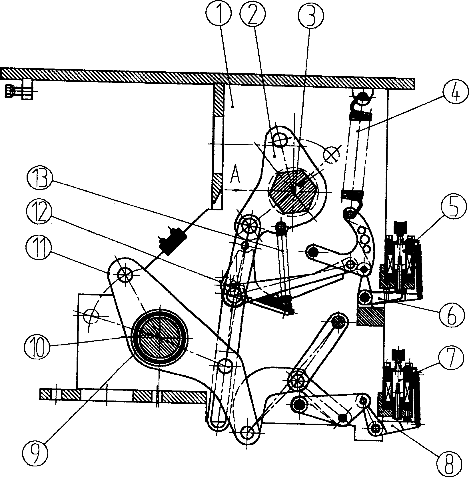
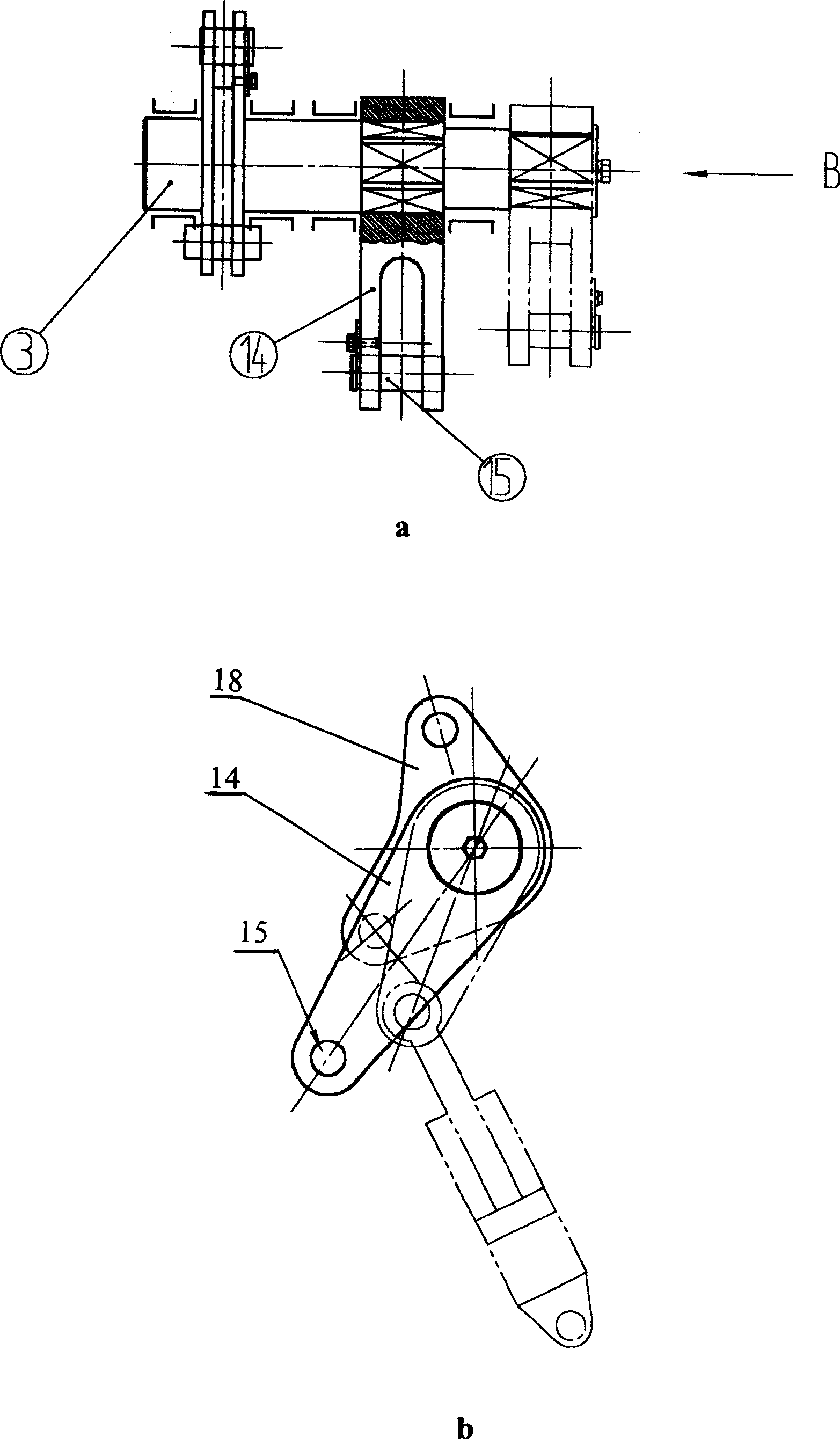
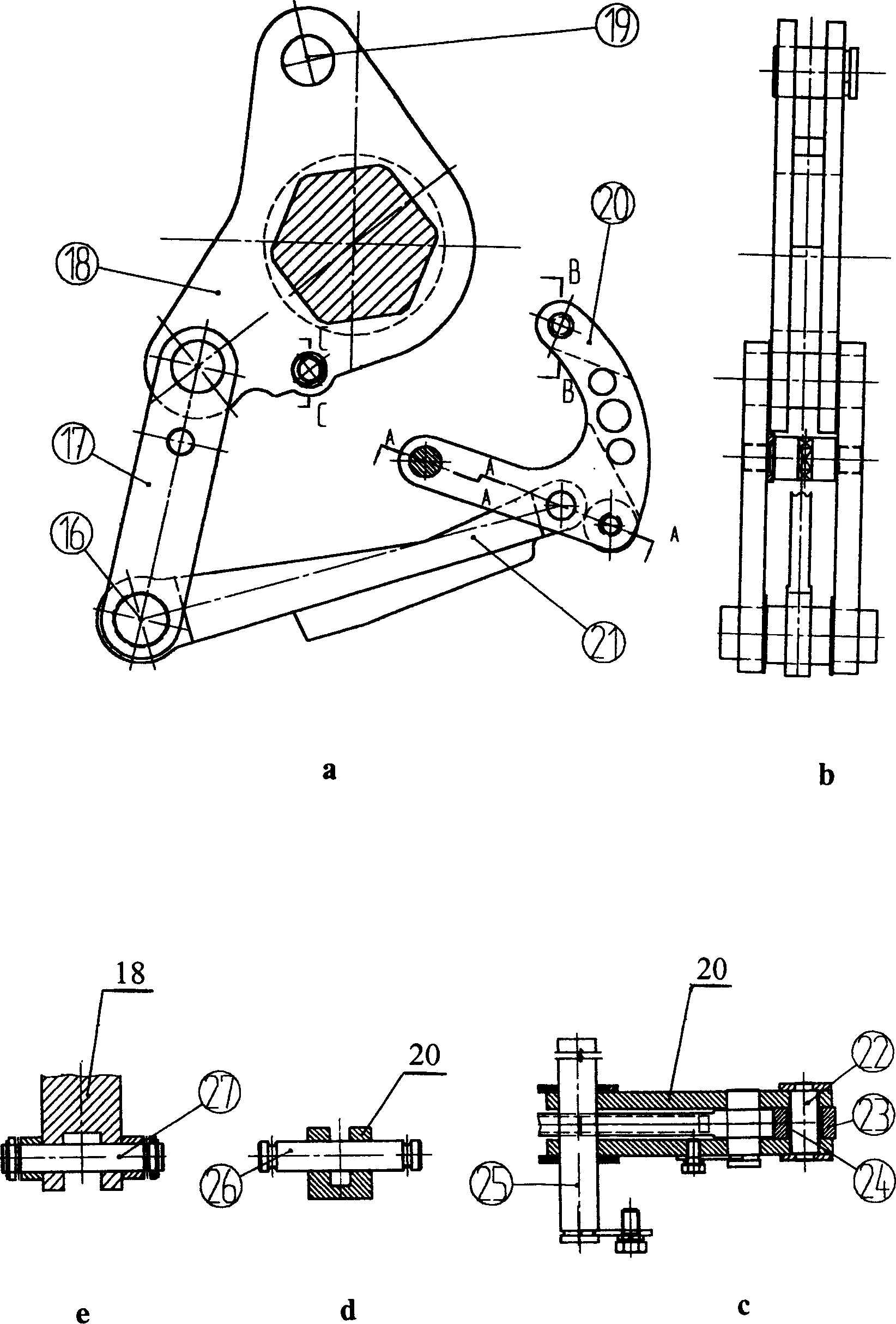
[0032] Depend on figure 1 As shown, the planar link mechanism in the transmission device of this embodiment is composed of a closing assembly 11 and an opening assembly 2 . The detailed structure of the opening assembly 2 is given by figure 1 , figure 2 with image 3 As shown, the crank arm 18 is installed on the output shaft 3, the output shaft 3 is hexagonal, and the crank arm 18 is fixedly connected with the output shaft. A crank arm 14 is also fixedly installed on the output shaft 3 at the same time, and the crank arm 14 is connected with the connecting rod of the circuit breaker through a pin shaft 15 . The pin hole at the upper end of the crank arm 18 is connected with the opening accumulator F through a pin shaft 19 . The pin hole of its lower end is connected with connecting plate 17 by bearing pin, and the pin hole of the left e...


PUM


Abstract

The equipment is composed of a set of planar linkage mechanism including two pieces of switch off detent and switch on detent supported on a releasing arrangement and controlled by electromagnet. The advantages of the invention are: simple mechanism, reasonable arrangement, and small vibration in operation process. The equipment can be applied to SF6 high voltage breaker with large power and good working performances and high reliability.

Description

technical field [0001] The invention belongs to an electric machine, in particular to a transmission and tripping device for transferring energy and controlling opening and closing actions in a spring operating mechanism of a high-voltage circuit breaker. Background technique [0002] At present, there are roughly four types of transmission devices in the operating mechanism of high-voltage circuit breakers used in China: 1. Pneumatic operating mechanism. 2. Hydraulic operating mechanism. 3. Spring hydraulic operating mechanism. 4. Spring operating mechanism. Due to the complex structure of the first three types of transmission devices, the unavoidable oil leakage and air leakage during operation, and the existence of problems such as high operating costs and failure rates, most people in the industry agree with the spring operating mechanism. Therefore existing multiple spring operating mechanisms have come out in succession in recent years. Although their structures ar...

Claims


Application Information

Patent Timeline
IPC IPC(8): H01H33/38H01H33/40
Inventor 黄伦
Owner 沈阳亚泰高压电力设备制造有限公司
Why Eureka
Try Eureka