Bladed disc machining center

A technology of machining centers and blisks, applied in metal processing equipment, metal processing machinery parts, manufacturing tools, etc., can solve problems such as difficult processing requirements

Pending Publication Date: 2020-05-08
KEDE NUMERICAL CONTROL CO LTD
View PDF0 Cites 1 Cited by
  • Summary
  • Abstract
  • Description
  • Claims
  • Application Information

AI Technical Summary

Problems solved by technology

It is easier to achieve such processing accuracy on the processing shape if the surface of the processing plane, cylindr

Method used


Image

  • Bladed disc machining center
  • Bladed disc machining center
  • Bladed disc machining center

Examples


Example Embodiment

[0024] In order to make the purposes, technical solutions and advantages of the embodiments of the present invention clearer, the technical solutions in the embodiments of the present invention will be clearly and completely described below with reference to the accompanying drawings in the embodiments of the present invention. Obviously, the described embodiments These are some embodiments of the present invention, but not all embodiments. Based on the embodiments of the present invention, all other embodiments obtained by those of ordinary skill in the art without creative efforts shall fall within the protection scope of the present invention.
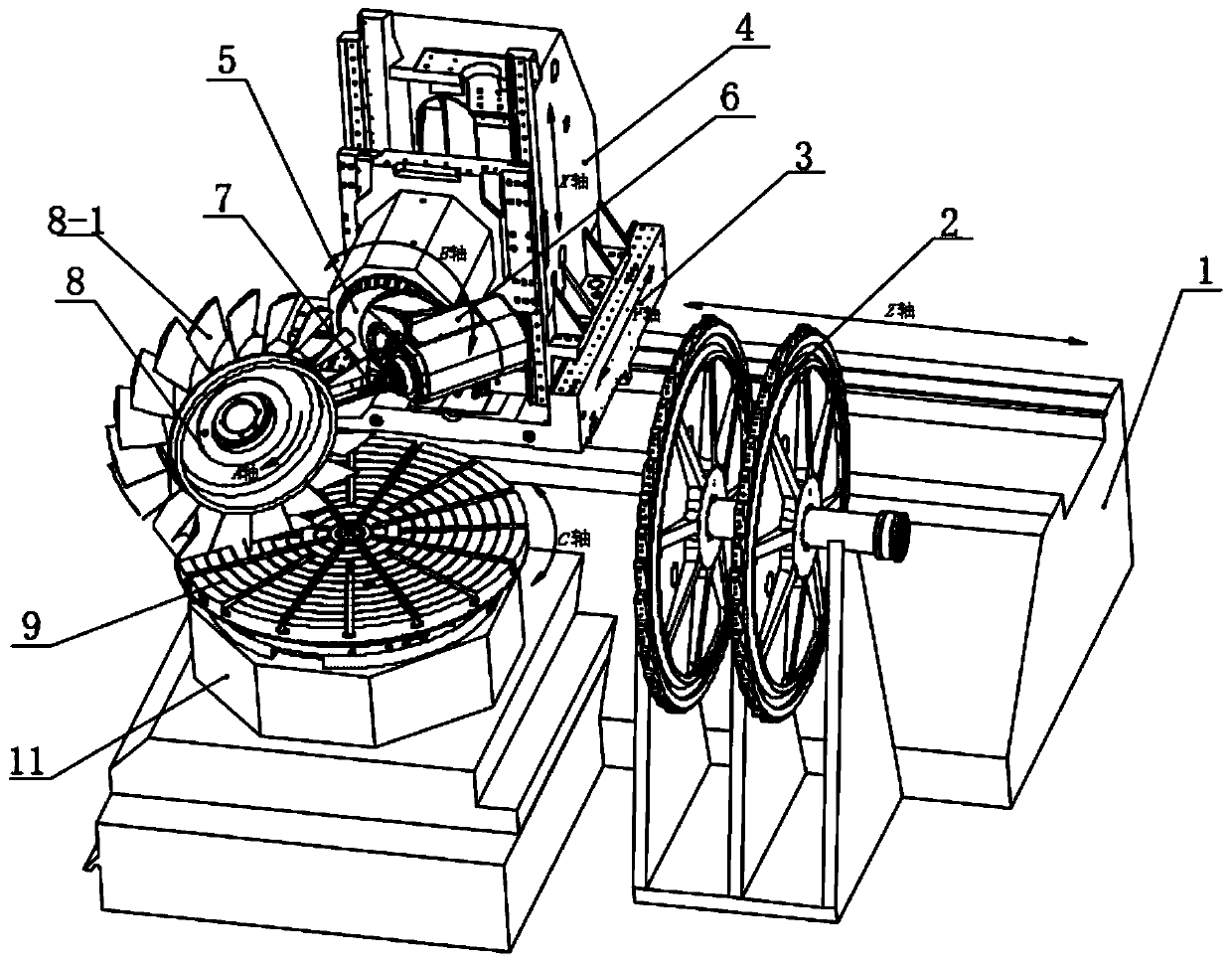
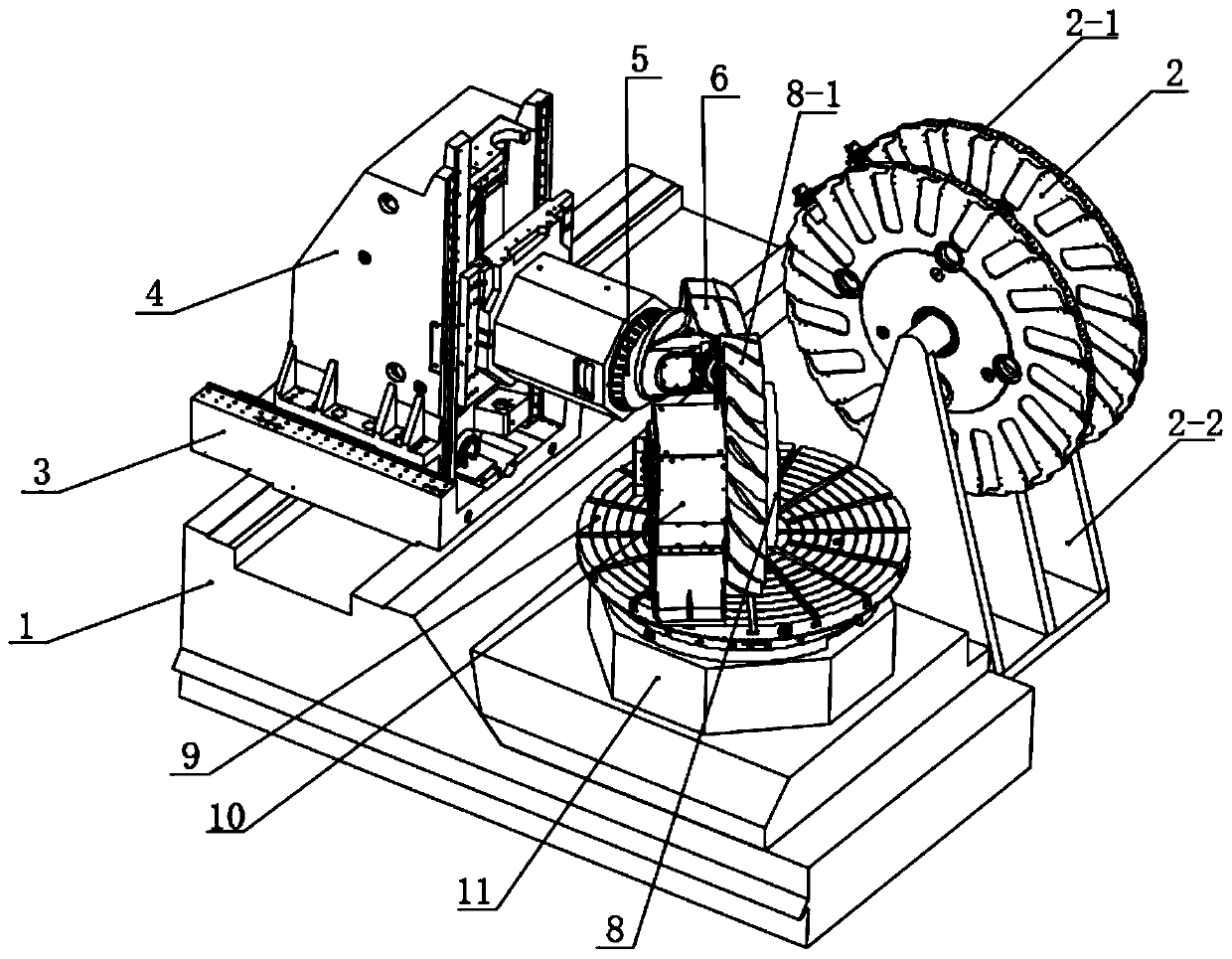
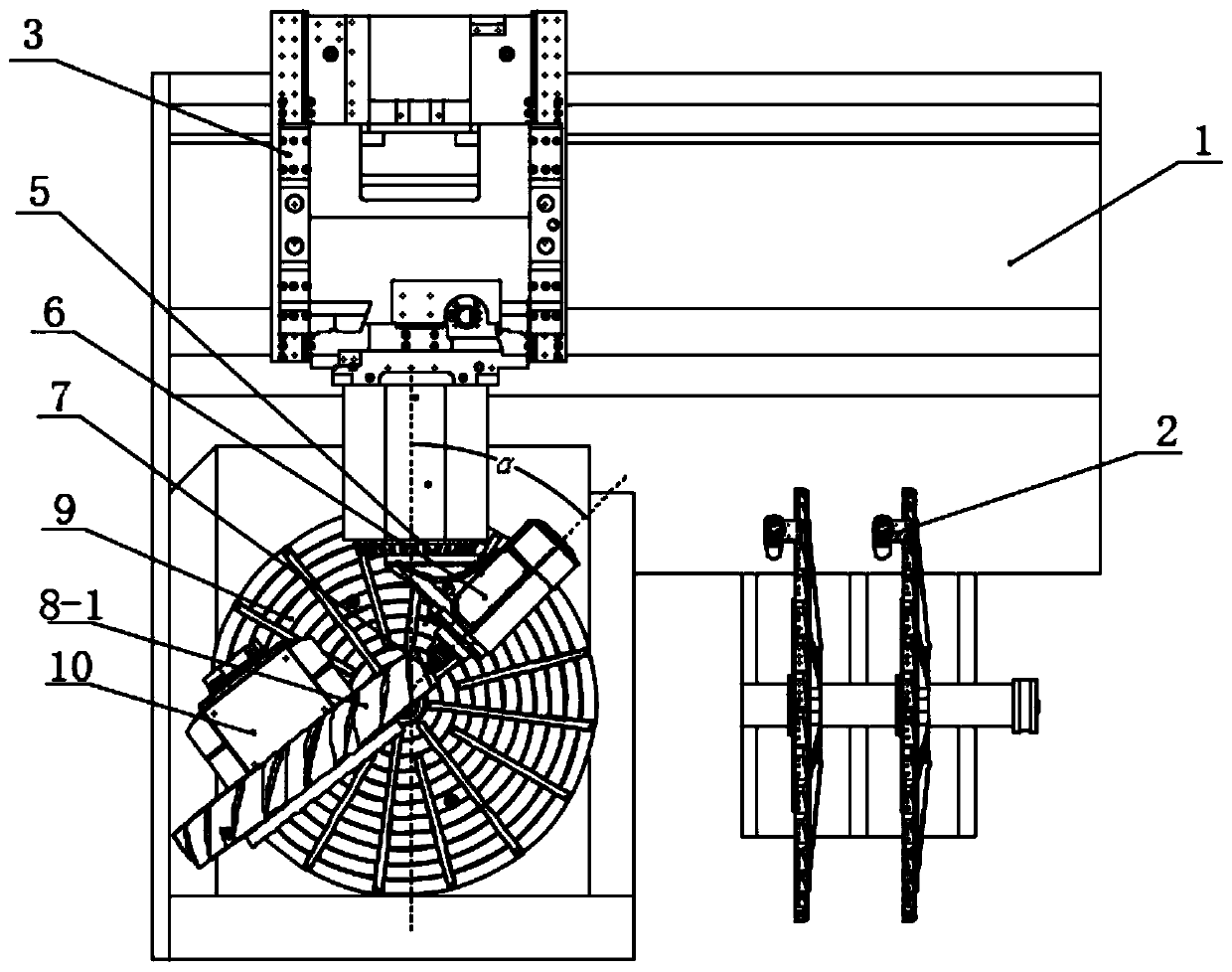
[0025] The present invention provides a blisk machining center, such as figure 1 As shown, it is a schematic diagram of the overall structure of the blisk machining center of the present invention; it includes: a bed 1, a sliding table 3, a column 4 and a ram; the sliding table 3 and the bed 1 are slidably connected through guide ra...


PUM


Abstract

The invention provides a bladed disc machining center. The bladed disc machining center comprises an A-axis rotary assembly, a B-axis rotary assembly and a C-axis rotary assembly, wherein the A-axis rotary assembly drives a blade disc to do rotary motion; the B-axis rotary assembly drives an accessory head to do rotary motion, and the accessory head drives a tool to machine the bladed disc; the C-axis rotary assembly drives the A-axis rotary assembly to do rotary motion; the intersection point of the rotating axis of the B-axis rotary assembly and the rotating axis of the C-axis rotary assembly is the center of the machining area of the bladed disc; and the tool nose point of the tool is on the rotating axis of the B-axis rotary assembly. According to the bladed disc machining center, themachining area is close to the rotating center of a C-axis rotary table, and it can be guaranteed that when a machine tool conducts five-axis rotating tool center machining action, the movement speedand acceleration of all physical axes can be kept within a low range compared with those of a machine tool of a common structure.

Description

technical field [0001] The invention relates to the field of machine tool processing, in particular to a blisk processing center. Background technique [0002] The use of blisks in aero-engines is the development trend of aero-engine technology in the world. In order to expand the application of blisks in aero-engines, the manufacturing problems of blisks must first be solved. At present, the number of blisks used in my country's aero-engines is small, and the main reason why they cannot be widely used is that the manufacturing technology of blisks has not yet been solved. The difficulty in manufacturing the blisk of an aero-engine lies in the complex profile of the blade, high processing accuracy and surface quality requirements, extremely high blade processing consistency, blade processing deformation, and the materials used. The blade surface of the overall blisk is mostly a free-form surface, and there are extremely high requirements on the machining accuracy and surfac...

Claims


Application Information

Patent Timeline
IPC IPC(8): B23Q5/22B23Q3/155
CPCB23Q5/22B23Q3/155B23Q2220/004B23Q2220/006B23Q1/52B23Q1/5437B23C3/18B23Q3/183F05D2230/10B23Q3/15706B23Q3/15539
Inventor 陈虎刘沛王连炀孙宏伟韦志鸿李少智汤洪涛林猛宋明山郭洪震高禄军
Owner KEDE NUMERICAL CONTROL CO LTD
Why Eureka
Try Eureka