Work machine having hydraulics for energy recovery

a work machine and energy recovery technology, applied in mechanical machines/dredgers, servomotors, construction, etc., can solve the problems of comparatively expensive and complex, and the solution is comparatively complex and expensiv

Active Publication Date: 2021-02-23
LEIBHERR HYDRAULIKBAGGER GMBH
View PDF4 Cites 1 Cited by
  • Summary
  • Abstract
  • Description
  • Claims
  • Application Information

AI Technical Summary

Benefits of technology

[0008]The additional second displacement unit accordingly serves not only for the energy recovery, but also acts as an additional work pump in the regular working mode, said work pump either assisting the first displacement unit or alternatively supplying separate consumers with energy.
[0009]It is characteristic for the solution in accordance with the invention that both the first displacement unit and the second displacement unit are parts of an open hydraulic circuit, i.e. the hydraulic actuator is supplied with energy via an open hydraulic circuit. The implementation of the solution in accordance with the invention thereby becomes a lot simpler in comparison with existing solutions of the prior art.
[0022]It is furthermore possible to arrange at least one proportionally controllable bypass valve at the outlet of the second ski selector valve, with the degree of opening of said bypass valve being increased by the machine control if the desired movement speed of the actuator cannot be reached in the recovery mode due to the volume flow restriction of the second displacement unit, i.e. the required volume flow at the outlet of the actuator would exceed the maximum possible volume flow of the second displacement unit. The excess volume flow can be conducted via the bypass into the hydraulic tank with the aid of the bypass valve so that a reaching of the desired movement speed of the actuator is ensured.

Problems solved by technology

Some of these solution approaches are based on a closed hydraulic circuit for the energy recovery; however, this is comparatively expensive and complex.
The electrics required for this also make this solution comparatively complex and expensive, in particular since the recovered energy first has to be buffered.

Method used


Image

  • Work machine having hydraulics for energy recovery
  • Work machine having hydraulics for energy recovery
  • Work machine having hydraulics for energy recovery

Examples


Embodiment Construction

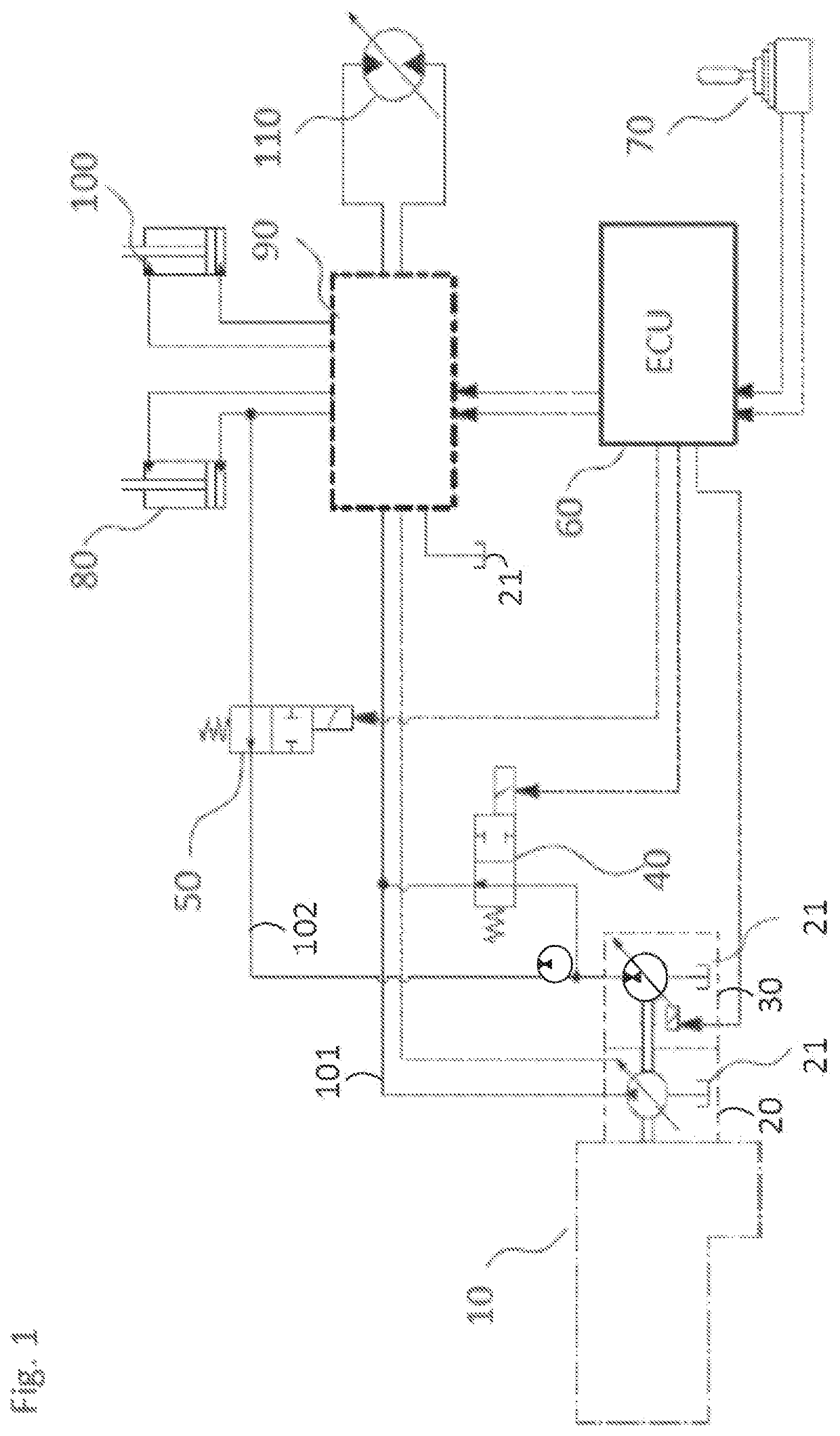
[0031]The basic operation of the present invention will be explained with reference to the outlined hydraulic circuit diagram of FIG. 1. Here, the control block 90 for the control of the hydraulic actuator 80 is not shown further, but the key idea of the invention should rather be independently explained with reference to the circuit diagram.

[0032]A linear actuator can be seen here in the form of a piston-in-cylinder unit 80 that serves the actuation of the excavator boom of the work machine in accordance with the invention. The required hydraulic pressure is provided by the main pump 20 that is driven via the central drive assembly 10. The pump 20 is designed as a variable delivery pump. The hydraulic circuit is configured as an open hydraulic circuit since the hydraulic pump 20 sucks in the required hydraulic medium from a tank 21 coupled to the pump 20 and supplies the linear actuator 80 with hydraulic energy via the control block 90. The feed pressure can be selectively supplied...


PUM


Abstract

The present invention relates to a work machine having at least one hydraulic actuator for actuating a piece of working equipment and having a first displacement unit that is driven by a drive assembly of the work machine and that feeds the hydraulic actuator with hydraulic medium from a hydraulic tank, wherein at least one second displacement unit is provided that is driven by the drive assembly and that feeds the hydraulic actuator and / or further hydraulic consumers with hydraulic medium from a hydraulic tank in the working mode and that is drivable during a recovery mode by the hydraulic volume displaced by the at least one hydraulic actuator or by a hydraulic consumer to feed kinetic energy back to the drive assembly.

Description

CROSS-REFERENCE TO RELATED APPLICATIONS[0001]The present application claims priority to German Application No. 10 2018 101 924.6 entitled “WORK MACHINE HAVING HYDRAULICS FOR ENERGY RECOVERY,” filed Jan. 29, 2018. The entire contents of the above-listed application are hereby incorporated by reference in their entirety for all purposes.TECHNICAL FIELD[0002]The invention relates to a work machine having at least one hydraulic actuator for actuating a piece of working equipment and having a first displacement unit that is driven by a drive assembly of the work machine and that feeds the hydraulic actuator with hydraulic medium from a hydraulic tank.BACKGROUND AND SUMMARY[0003]An example for a corresponding work machine is a hydraulic excavator whose boom arm can be actuated by means of a hydraulic linear actuator such as a piston-in-cylinder unit. Hydraulic energy typically does not have to be applied for the lowering of the boom since the boom can lower due to the load. It is desirabl...

Claims


Application Information

Patent Timeline
Patent Type & Authority Patents(United States)
IPC IPC(8): F15B21/14
CPCF15B21/14F15B2211/20569F15B11/17E02F3/43E02F3/435F15B2211/20576E02F9/2292F15B2211/20515F15B2211/20523F15B2211/20546F15B2211/212F15B2211/3111F15B2211/40515F15B2211/41509F15B2211/41572F15B2211/41581F15B2211/426F15B2211/6346F15B2211/6651F15B2211/6652F15B2211/6658F15B2211/7053F15B2211/7058F15B2211/7135F15B2211/75F15B2211/761E02F9/2217E02F9/2296E02F9/2235
Inventor MEITINGER, BERNHARDWIRTHENSOHN, MANUEL
Owner LEIBHERR HYDRAULIKBAGGER GMBH
Why Eureka
Try Eureka