Receiver-autonomous vertical integrity monitoring

A technology of integrity and receiver, applied in the field of methods and systems, which can solve problems such as compatibility of airborne equipment

A technology of integrity and receiver, applied in the field of methods and systems, which can solve problems such as compatibility of airborne equipment

CN1481522AInactive Publication Date: 2004-03-10UNITED PARCEL SERVICE OF AMERICAN INC

Image

  • Receiver-autonomous vertical integrity monitoring
  • Receiver-autonomous vertical integrity monitoring
  • Receiver-autonomous vertical integrity monitoring

Examples


Embodiment Construction

[0036] The invention will be described in more detail below with reference to the accompanying drawings, which show preferred embodiments of the invention. However, the invention may be embodied in many different forms and should not be construed as limited to the embodiments set forth herein; The scope of the present invention will be clearer to those skilled in the art. Like numbers refer to like elements throughout.

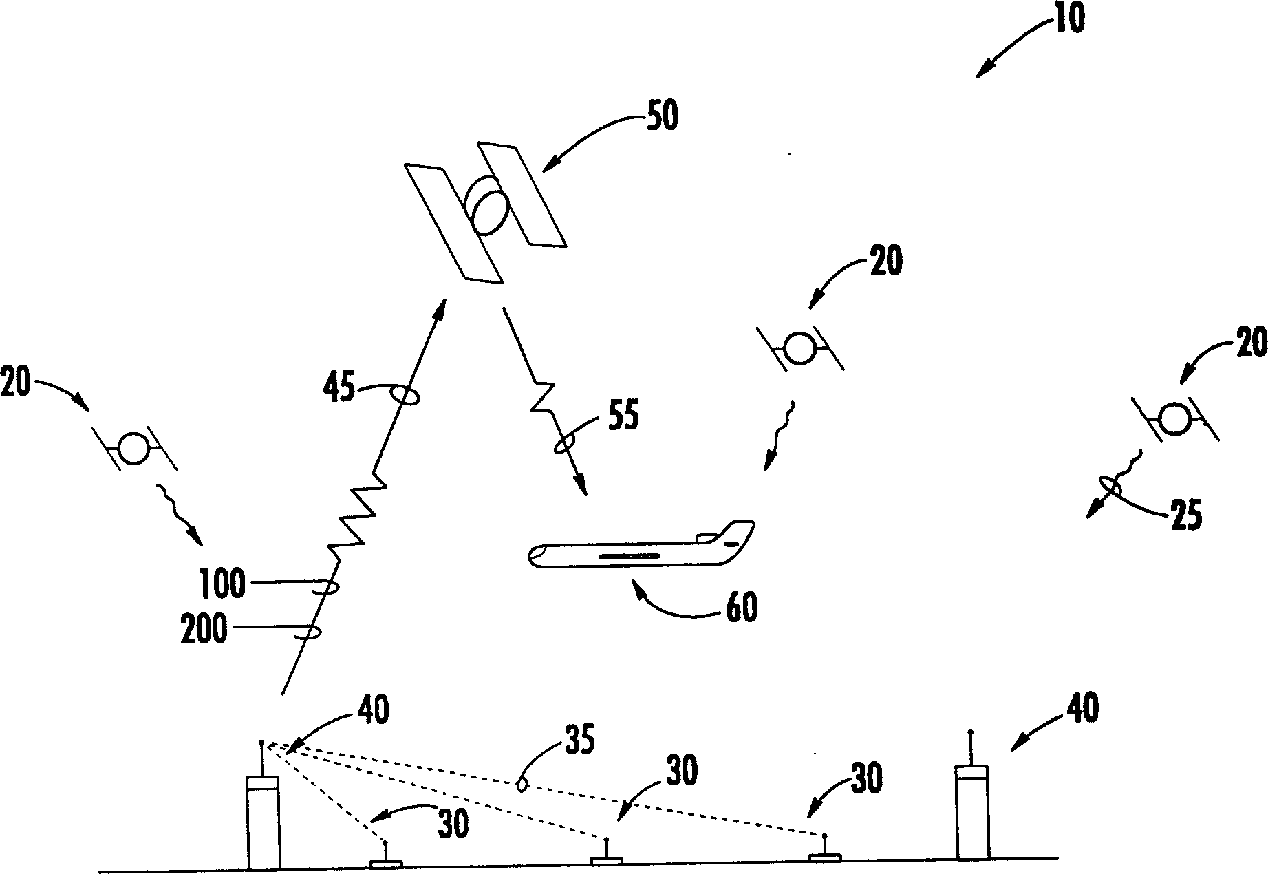
[0037] figure 1 A schematic diagram of the various components of a wide area augmentation system (WAAS) 10 is shown. WAAS is an example of an aircraft navigation broadcast system in which the broadcast signal has an altitude component, other navigation broadcast systems with an altitude component are also suitable for vertical integrity and fall within the inventive concepts disclosed herein. An existing array of GPS satellites 20 continuously broadcasts GPS signals 25 to an array of ground-based reference stations 30 . Ground-based reference station 30 br...


PUM


Abstract

A system and method for determining the vertical integrity of an altitude component of an aircraft navigational signal through the use of a receiver-autonomous vertical integrity monitoring (RAVIM) algorithm. The system and methods also provide timely warning to vehicle operators if the integrity of the signal is unacceptable or unknown. The system and methods are capable of determining the vertical integrity of an incoming signal without relying upon data embedded within the incoming signal itself. In addition, the system and methods of the present invention provide vertical integrity to vehicle operators in instances, such as when the specific aircraft navigational signal is not operating, when the specific aircraft navigational signal is not available in a particular region, or when an aircraft is operating outside the geographic area covered by the specific aircraft navigational signal system.

Description

technical field [0001] The present invention relates generally to the field of aircraft navigation systems. More specifically, the present invention includes a method and system for determining the vertical integrity of a broadcast signal, particularly a WAAS-enhanced GPS signal, without relying on data embedded in the broadcast signal itself. Background technique [0002] High-quality navigation data is critical to flying safely, especially given the increase in air traffic worldwide. Aircraft navigation has evolved to rely more and more on signals from orbiting satellites. Satellite navigation offers greater precision than traditional land-based methods, but it also comes with many technical challenges. The latest airborne avionics, from receivers to cockpit displays, require position data that is highly accurate, widely available and constantly monitored to ensure its integrity. [0003] The Global Positioning System (GPS) is a satellite network activated by the United...

Claims


Application Information

Patent Timeline
10 Mar 2004
Publication
CN1481522A
IPC
G01C21/00; B64D45/00; G01S19/07; G01S19/11; G01S19/12; G01S19/31; G08G5/00
CPC
G05D1/0607
Inventors
罗伯特·C·赫尔伯