Topology-driven apparatus, method and computer program product for developing a wiring design

a topology-driven, wiring design technology, applied in the direction of static indicating devices, instruments, manufacturing tools, etc., can solve the problems of manual development of wiring designs, serial and often with a high rate of change, repetitive development, and the inability to overcome process and tool shortcomings, so as to facilitate effective implementation of design process/standards/constraints, enhance/maintain the design and data integrity

Active Publication Date: 2007-06-21
THE BOEING CO
View PDF13 Cites 24 Cited by
  • Summary
  • Abstract
  • Description
  • Claims
  • Application Information

AI Technical Summary

Benefits of technology

[0009] As the electrical wiring design is developed and matured in accordance with exemplary embodiments of the present invention, business / design rule-based constraints, scripts, wizards and / or checks / audits (e.g., separation / protection, routing, part selection, termination, etc.) can be dynamically applied to facilitate effective implementation of design processes / standards / constraints and design data configuration control / management. Such dynamic interaction of the rule sets during the design development may reduce, if not eliminate, manual / visual validation and verification of requirements, and / or may enhance / maintain the design and data integrity.

Problems solved by technology

Conventionally, such wiring designs have been developed manually, serially and often with a high rate of change.
Conventional techniques for developing large-scale system-level wiring harness designs are often very complex, repetitive and based on large numbers of design artifacts such as virtual and hardcopy documents, i.e., schematic diagrams, data tables, instructional text, exploded graphic views, and so forth.
Whereas techniques for developing large-scale system-level wiring designs such as that described above are adequate, such techniques have drawbacks and require manpower to overcome the process and tool shortcomings.
As a result of re-entry of the same data in multiple computing systems, the error rate in harness designs can be very high.
And as the engineer is typically never sure that the entire design intent of a system change has been included in the wiring design or redesign, and if any information is missing, that information is typically not discovered until functional testing of the system is performed after the installation into the product.
A high rate of change in re-engineered wire harnesses is non-value added work because of multiple baselines used by the system designers.
As a consequence, the high rate of change in wiring configuration often leads to out-of-sequence work and has a very large impact on the downstream customers of wire harnesses, such as manufacturing, fabrication and installation processes and products.

Method used


Image

  • Topology-driven apparatus, method and computer program product for developing a wiring design
  • Topology-driven apparatus, method and computer program product for developing a wiring design
  • Topology-driven apparatus, method and computer program product for developing a wiring design

Examples


Embodiment Construction

[0024] The present invention now will be described more fully with reference to the accompanying drawings, in which some, but not all embodiments of the invention are shown. This invention may be embodied in many different forms and should not be construed as limited to the embodiments set forth; rather, these embodiments are provided so that this disclosure will be thorough and complete, and will fully convey the scope of the invention to those skilled in the art. Like numbers refer to like elements throughout.

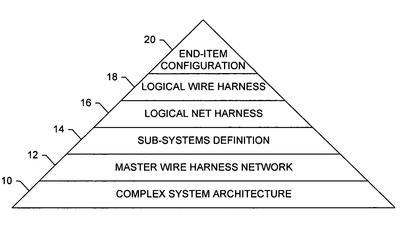
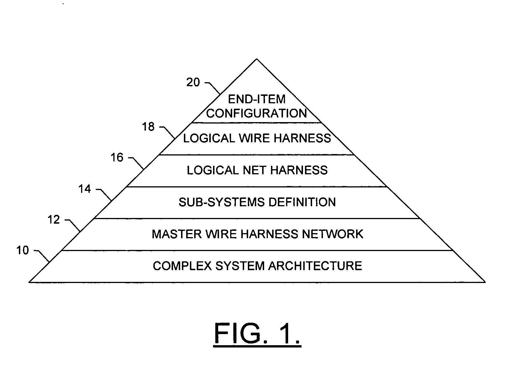
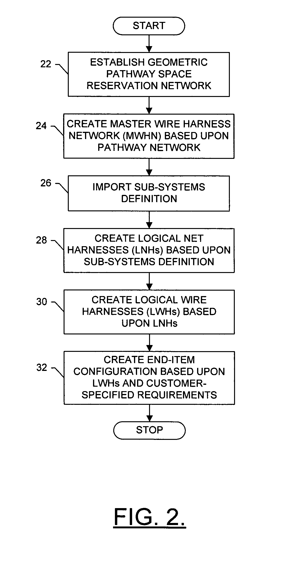
[0025] Referring to FIGS. 1 and 2, a hierarchical organization and flowchart are presented for developing a wiring design for a complex system, in accordance with exemplary embodiments of the present invention. At the outset, it is important to note that exemplary embodiments of the present invention may be implemented to develop a wiring design for any type of simple or complex system. The network system may be resident in an automobile, aircraft, spacecraft, vehicle, build...


PUM

PropertyMeasurementUnit
physicalaaaaaaaaaa
physical shapeaaaaaaaaaa
local area networkaaaaaaaaaa

Abstract

A method for developing a wiring design for a complex system includes creating a master wire harness network (MWHN) within pathway space reservations of a pathway space-reservation network of the complex system. In this regard, the MWHN can comprise a model of possible wiring pathways between equipment of the complex system, and can include wire harness elements interconnecting termination device elements. The method can also include importing a subsystems definition capable of being represented by interconnections between the equipment. Thus, one or more logical net harnesses (LNHs) can be created based upon the MWHN and the subsystems definition. The LNH, then, can comprise a collection of interconnections routed within the MWHN. One or more logical wire harnesses (LWHs) can be created based upon the LNHs, after which one or more end-item configurations (EICs) can be created based upon the LWHs.

Description

FIELD OF THE INVENTION [0001] The present invention relates generally to apparatuses and methods for developing wiring designs to integrate systems definitions within a large-scale, complex system of systems and, more particularly, to topology-driven apparatuses and methods for developing wiring designs to integrate systems definitions. BACKGROUND OF THE INVENTION [0002] Large-scale system integration (such as an airplane, space shuttle, space station, ship, submarine, helicopter, power plant, large complex building, aircraft carrier, or the like) is typically a complex undertaking. In this regard, such large-scale systems (sometimes referred to as a “system of systems”) often include a working conglomeration of smaller-scale systems (systems), which themselves often include even smaller-scale systems (subsystems), and so forth. Notwithstanding the necessity of building, retaining, and imparting an overall vision of a large-scale system, it is nevertheless imperative that such a sys...

Claims


Application Information

Patent Timeline
Patent Type & Authority Applications(United States)
IPC IPC(8): H01R11/00
CPCG06F17/509G06F2217/36Y10T29/49163Y10T29/49174Y10T29/53209Y10T29/49181Y10T29/4919G06F30/18G06F2113/16
Inventor SAINI, SATPALFONDEN, RONALD G.RIEDL, PATRICK H.HONG, SEWONMOORE, TERESA A.SHAPPELL, PAUL E.
Owner THE BOEING CO
Why Eureka
Try Eureka