Vorticity compression pump

A technology of turbo compressor and compression mechanism, applied in the field of turbo compressor

Inactive Publication Date: 2004-03-17
HITACHI JOHNSON CONTROLS AIR CONDITIONING INC
View PDF1 Cites 25 Cited by
  • Summary
  • Abstract
  • Description
  • Claims
  • Application Information

AI Technical Summary

Problems solved by technology

That is, the subject of research is to reduce the outflow of refrigerating machine oil to the external circulation at low cost and within the range of assumed operating conditions

Method used


Image

  • Vorticity compression pump
  • Vorticity compression pump
  • Vorticity compression pump

Examples


Embodiment Construction

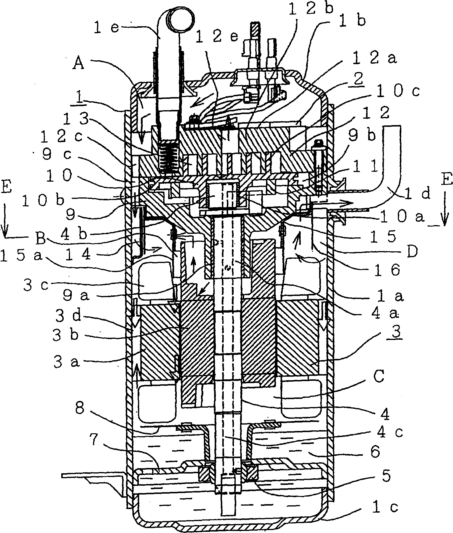
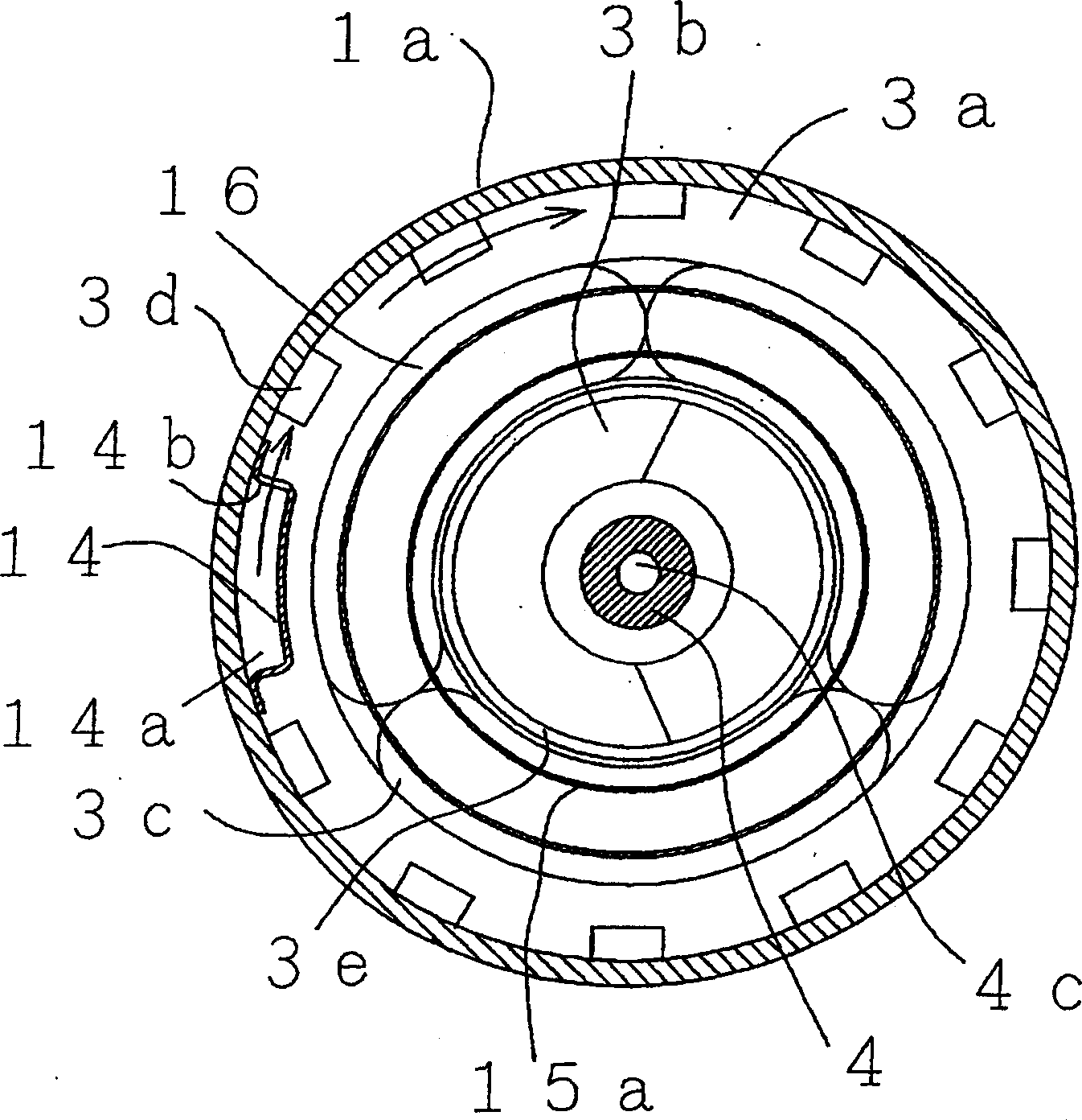
[0015] Below, refer to Figure 1 to Figure 6 One embodiment to which the turbo compressor of the present invention is applied will be described. exist figure 1 Among them, the compression mechanism 2 is arranged on the upper part of the airtight container 1, the electric motor 3 is arranged on the lower part, and the crankshaft 4 is connected up and down. The stator 3a of the electric motor 3 is fixed in the case 1a of the airtight container 1 by heat fitting or the like, and the rotor 3b of the electric motor 3 is fixed by, for example, the crankshaft 4 being press-fitted.

[0016] The airtight container 1 is based on a cylindrical shell 1a, a double chamber 1b is welded on the upper part, and a bottom chamber 1c is welded on the lower part. An exhaust pipe 1d is installed on the side of the casing 1a, and a suction pipe 1e is installed on the double chamber 1b to connect the respective compression mechanisms 2.

[0017] The compression mechanism 2 has a frame 9 on which a...


PUM


Abstract

Provided is a scroll compressor in which spillage of refrigerating machine oil into external cycle is reduced in low cost and assumable service condition range. The scroll compressor applies extreme flow rate differences to oil which has been mixed into discharge gas in the form of mist by making the oil flow in into a large cross-sectional area passage from a narrow passage at the initial stage of discharge gas circulating route, converts flow direction by using a current transformer, and liquefies and separates the oil mist by making the discharge gas collide with sealed container inner wall. Further, the compressor liquefies and separates oil mist permeating inside an end coil of a motor or lubricating oil flowing in from a bearing by making them collide with an oil cover partitioning outer diameter section (end coil inner diameter of a stator) of the rotor in such a manner that they are led to a rotating portion of a rotor to be applied by centrifugal force.

Description

technical field [0001] The present invention relates to a turbo compressor for compressing refrigerant gas in a room air conditioner or the like. Background technique [0002] During the operation of the refrigerant compressor in the refrigeration cycle, the refrigerating machine oil used for lubricating the sliding part of the compression mechanism such as the gasket or the bearing is mixed into the compressed gas in the compression mechanism or by becoming mist, or passing through the gap from the bearing. sprayed out and mixed into the exhaust. When the exhaust gas mixed with such oil mist flows into the piping of the refrigeration cycle through the exhaust pipe of the compressor, the mist oil liquefies and adheres to the inside of the piping. In the case of heat exchanger piping, the attached oil acts as a heat-insulating layer, impeding heat exchange performance, obstructing ventilation in other piping, causing pressure loss, and reducing the heat exchange efficiency o...

Claims


Application Information

Patent Timeline
Patent Type & Authority Applications(China)
IPC IPC(8): F04C29/02F04C18/02
Inventor 大沼敦田村和巳小山昌喜关上和夫坪野勇小田岛毅
Owner HITACHI JOHNSON CONTROLS AIR CONDITIONING INC
Why Eureka
Try Eureka