Microflute evaporating and cooling method and apparatus using same

A technology of evaporative cooling and cooling method, applied in the field of evaporative cooling method of computer chip and its device, can solve the problems of large heat dissipation area, insufficient heat dissipation capacity, small heat dissipation area, heat flux density and total heat dissipation capacity, etc., and achieve heat dissipation without power consumption The effect of improving the total cooling and heat dissipation capacity and improving the working performance

Inactive Publication Date: 2004-03-17
SINO TECH INVESTMENT HLDG
View PDF0 Cites 7 Cited by
  • Summary
  • Abstract
  • Description
  • Claims
  • Application Information

AI Technical Summary

Problems solved by technology

[0003] The invention solves the technical defects of high power consumption requirement, large heat dissipation area and insufficient heat dissipation capacity in the existing air-cooled heat dissipation technology, and provi

Method used


Image

  • Microflute evaporating and cooling method and apparatus using same
  • Microflute evaporating and cooling method and apparatus using same
  • Microflute evaporating and cooling method and apparatus using same

Examples


Embodiment 1

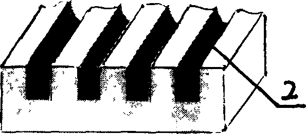
[0030] Embodiment 1: On metal plate or other heat-conducting materials, mark many rectangular microgrooves 2, form microgroove group, this heat exchange structure with microgroove group is called microgroove group heat sink, see figure 1 . figure 1 The medium and micro channels 2 are vertically densely arranged. The channel width and channel depth of the micro-channel 2 are in the range of 0.01-1 mm, and are rectangular micro-channels. The distance between the micro-channels is in the range of 0.01-10mm. The micro-channels 2 in this range have capillary attraction for various working fluids such as absolute ethanol or distilled water. More optimally, the width of the micro-channels and The depth is in the range of 0.01-0.6mm, and the distance between the micro-channels is in the range of 0.01-10mm. When the metal plate and the heating element are closely pasted by heat-conducting silica gel (silicon grease), the heat generated by the heating element is transferred to the met...

Embodiment 2

[0031] Embodiment 2: Directly engrave many microgrooves 2 on the outer surface of chips or other heating elements to form microgrooves groups, and the parts carved with microgrooves of heating elements such as chips become heat sinks of microgrooves groups. The size of the microchannel of the present embodiment is the same as that of embodiment 1, and the microchannel has capillary force equally, so that the liquid working medium is sucked into the heated area in the microchannel 2 and evaporated so as to take away the heat generated by heating elements such as chips.

Embodiment 3

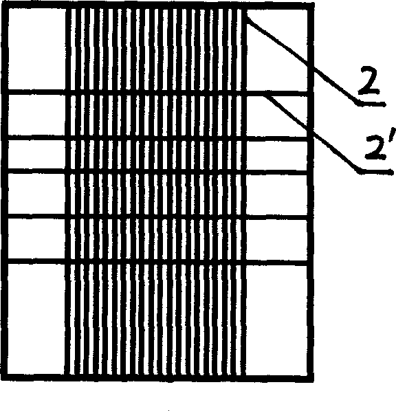
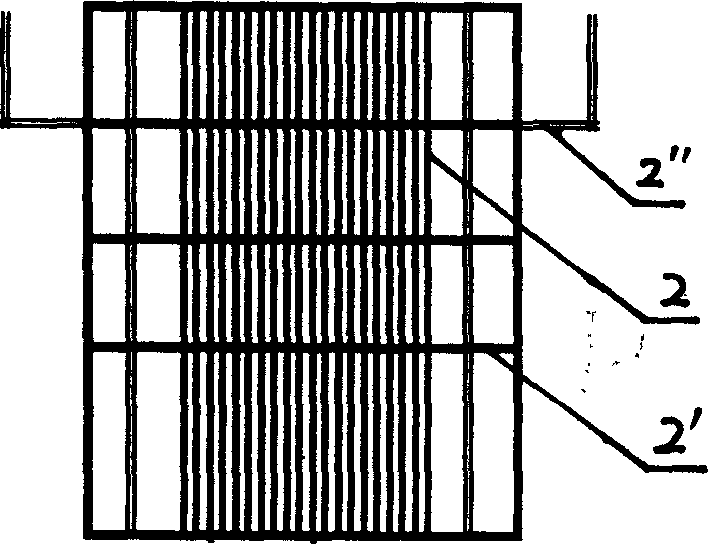
[0032] Embodiment 3: see figure 2 : the micro-channels 2 of the micro-groove group heat sink of the present embodiment are vertically densely arranged, and the vertically densely arranged micro-channels 2 are cross-arranged with transverse micro-channels 2 '. Arranging the microchannels 2' arranged horizontally can absorb more liquid working fluid to the heating area, so that the evaporated liquid working medium can be replenished in time, thereby improving the cooling efficiency. In this embodiment, the groove width of the microchannel 2 is 0.2mm, the groove depth is 0.5mm, and the groove spacing is 0.2mm, and the groove width of the transverse microchannel 2' is 0.4mm, the groove depth is 0.8mm, and the groove spacing is 5mm.


PUM

PropertyMeasurementUnit
Depthaaaaaaaaaa
Depthaaaaaaaaaa

Abstract

A microflute group heat-sink cooling method characterized by that, a plurality of microflutes are arranged at the radiating region near the external surface of the heater forming a microflute group, the liquid actuating medium in the microflutes can form high-intensity evaporation at the heated region for removing heat produced by the heater, thus cooling the heater through evaporation. The advantages of the invention are no power consumption, small heat dissipation area, high heat dissipation flow density and high intensity of heat.

Description

Technical field: [0001] The invention relates to a heat radiation cooling method, in particular to an evaporation cooling method and a device applied to computer chips. Background technique: [0002] At present, the cooling of the heating element, especially the CPU chip of the computer, mainly adopts heat sinks in combination with fans for air cooling. This technology reduces thermal resistance by attaching cooling fins on the surface of the CPU chip and applying heat-conducting silica gel (silicon grease) on the contact surface of the two. The heat exported by the CPU is dissipated to the environment of the computer case through the surface of the fins, so as to ensure that the CPU chip works within the normal operating temperature range. The main defect of this technology is: there is power consumption in the operation of the fan, because the higher the main frequency of the CPU, the greater the heat that the CPU needs to dissipate to maintain the normal operating temper...

Claims


Application Information

Patent Timeline
IPC IPC(8): G06F1/20H01L23/34
CPCY02B60/1275Y02D10/00
Inventor 赵耀华胡学功
Owner SINO TECH INVESTMENT HLDG
Why Eureka
Try Eureka