Supercharge Your Innovation With Domain-Expert AI Agents!

CMOS photo-sensor and operating method thereof

A technology of optical sensor and operation method, applied in the direction of recording/reproducing by optical method, optical recording/reproducing/erasing method, instrument, etc., can solve problems such as data distortion

Inactive Publication Date: 2004-03-17
SILICON OPTRONICS +1
View PDF0 Cites 0 Cited by
  • Summary
  • Abstract
  • Description
  • Claims
  • Application Information

AI Technical Summary

Problems solved by technology

However, since the general capacitor will have leakage (leakage), once the potential storage time in the capacitor is prolonged, the leakage will become more serious, and the stored data (potential) will also have severe distortion

Method used


Image

  • CMOS photo-sensor and operating method thereof
  • CMOS photo-sensor and operating method thereof
  • CMOS photo-sensor and operating method thereof

Examples


Embodiment Construction

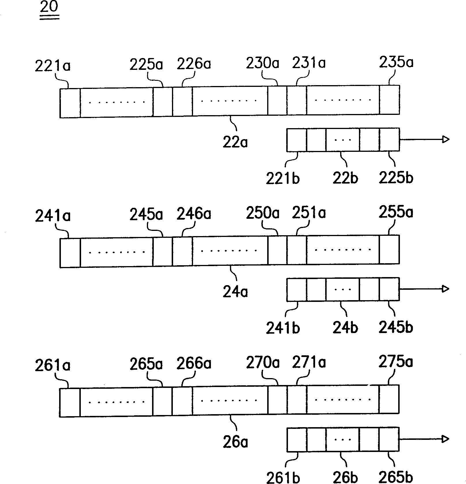
[0029] Please refer to figure 2 , which shows a schematic diagram of the relationship between the photo-sensing lines and the capacitor columns in the linear CMOS photosensor according to a preferred embodiment of the present invention. In the CMOS light sensor 10, it includes light sensing lines 22a, 24a and 26a for respectively sensing the three primary colors of red (R), green (G) and blue (B). Capacitive columns 22b, 24b and 26b of potentials generated by the light sensing lines 22a, 24a and 26a. Since the three photo-sensing lines 22a, 24a and 26a and the corresponding capacitor columns 22b, 24b and 26b have substantially the same operational relationship, only one group of photo-sensing lines and capacitor columns will be further described here.

[0030] Such as figure 2 As shown, in this embodiment, it is assumed that the number of capacitors 221 b - 225 b included in the capacitor column 22 b is one-third of the sensing units 221 a - 235 a in the light sensing line...


PUM


Abstract

The invention discloses a CMOS photo-sensor and method of operation thereof, wherein the CMOS photo-sensor has a photo-sensing wire and capacitance column, which contains a plurality of optical sensing units, the number of the capacitance column is less than the number of the optical sensing units on one optical sensing wire, for storing part of the electric potential produced by the optical sensing units as the light ray induction. The operational method for the CMOS photo-sensor can store the data in the optical sensing wire in segment into the capacitor column and fetching in turn, thus reducing the chance of capacitor leakage. íí

Description

technical field [0001] The invention relates to a CMOS light sensor and its operation method, and in particular to a CMOS light sensor which can be processed in sections and its operation method. Background technique [0002] Existing light sensors can generally be classified into two types: Charge Coupled Device (CCD) sensors and CMOS light sensors. In a traditional CCD sensor, a set of shift registers will be assigned to each light sensing line, and this set of shift registers is used to store the charge obtained by the CCD light sensing line due to the intensity of the sensed light, and will These charges are sequentially shifted out of the shift register and sent to the next stage of processing circuit. Similarly, if figure 1 As shown, in the current CMOS photosensor 10, each light sensing line (12a, 14a and 16a) is also equipped with a group of devices similar to the function of the aforementioned shift register, and these devices with similar functions Composed of c...

Claims


Application Information

Patent Timeline
IPC IPC(8): G11B7/004G11B7/13
Inventor 林敏哲陈世煌
Owner SILICON OPTRONICS
Features
  • R&D
  • Intellectual Property
  • Life Sciences
  • Materials
  • Tech Scout
  • Unparalleled Data Quality
  • Higher Quality Content
  • 60% Fewer Hallucinations
Learn More