
Group delay test method and device thereof

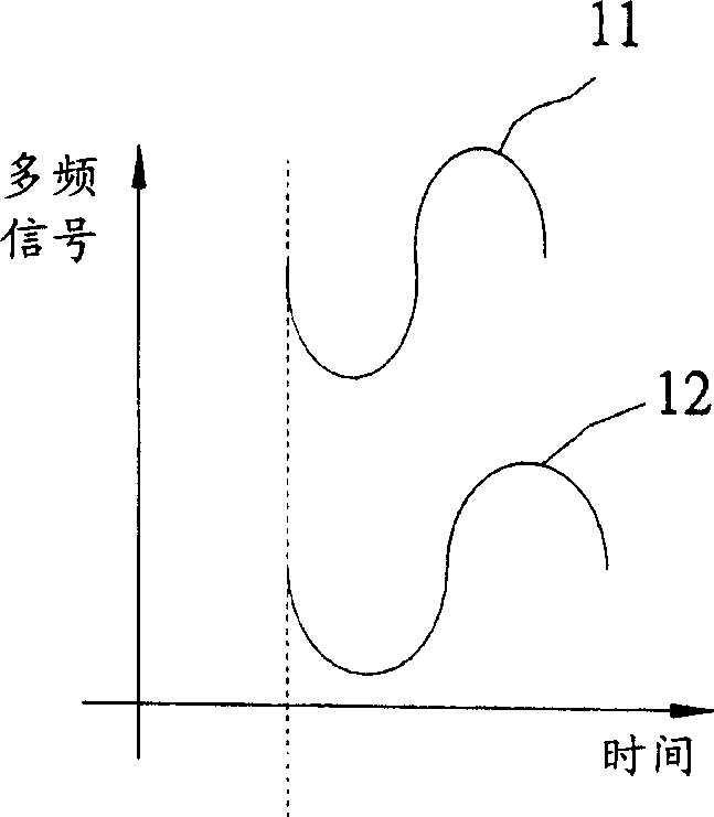
A test method and test device technology, applied in the direction of electronic circuit test, error detection/correction, transmission system, etc., can solve the problems of expensive and high cost of high-speed digitizer and high-resolution test instrument

Inactive Publication Date: 2004-03-24
MEDIATEK INC
View PDF0 Cites 15 Cited by
  • Summary
  • Abstract
  • Description
  • Claims
  • Application Information

AI Technical Summary

Problems solved by technology

[0009] 4 The aforementioned high-speed digitizers and high-resolution test instruments are very expensive, so a higher cost must be spent

Method used


Image

  • Group delay test method and device thereof
  • Group delay test method and device thereof
  • Group delay test method and device thereof

Examples


Embodiment Construction

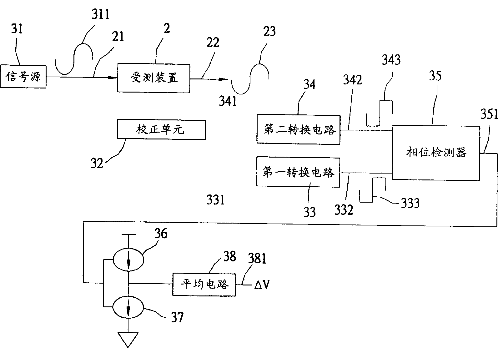
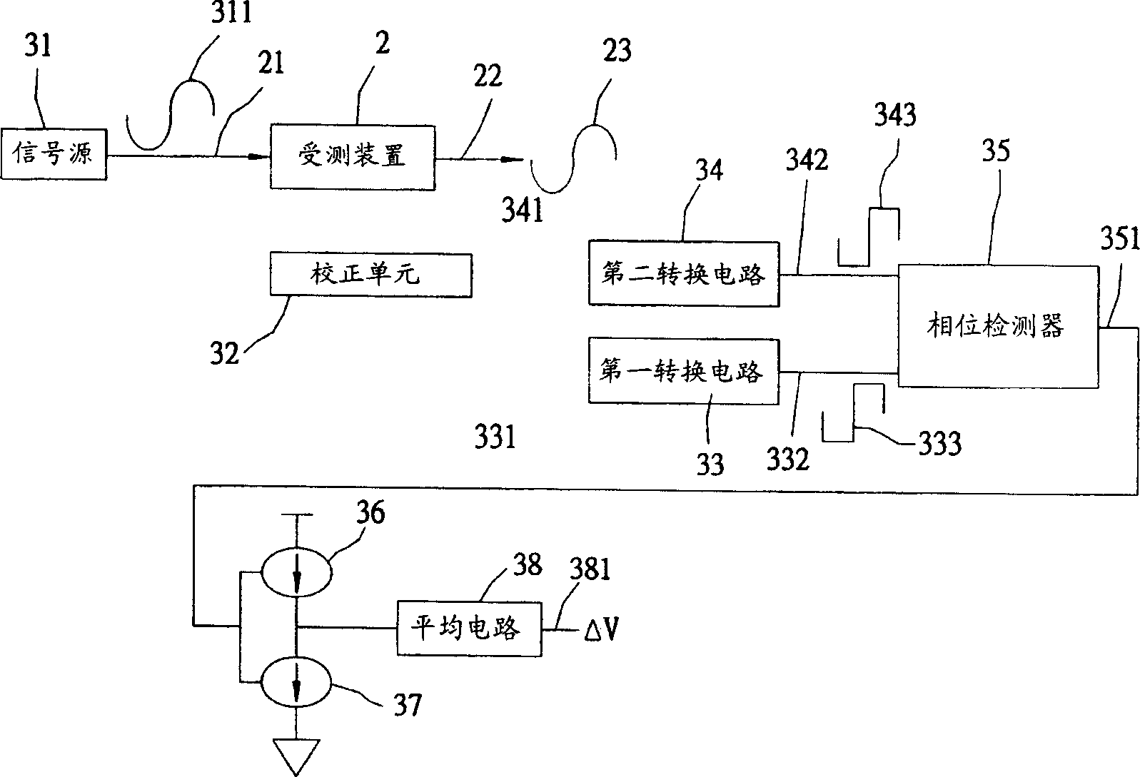
[0017] refer to figure 2 , is a schematic diagram of a test device for implementing the above group delay test method according to an embodiment of the present invention. The test device is pre-connected with a device under test 2 for measuring the group delay T of the device under test 2 gd .

[0018] The testing device includes a signal source 31 , a calibration unit 32 , a first conversion circuit 33 , a second conversion circuit 34 , a phase detector 35 , an upper current pump 36 , a lower current pump 37 and an average circuit 38 .

[0019] The signal source 31 can output an analog single-frequency signal 311 and supply the single-frequency signal 311 to an input terminal 21 of the device under test 2 . In this embodiment, the single-frequency signal 311 is a sine wave signal with a known period of T. After the single-frequency signal 311 passes through the device under test 2, it is output from an output terminal 22 of the device under test 2 after a delay. Single fr...


PUM


Abstract

The invention provides a group delay method to test the group delay Tgd. It includes the steps: (A) inputting a known period-T analog single-frequency signal to one input end of the tested device; (B) extracting the input single frequency and the output delayed one and converting them into a first digital signal and a second one, respectively; (C) comparing phase difference of the first and second signals; (D) converting the comparing result into a current I in direct proportion to the phase difference; (E) making the current I flow through a average circuit with a value-known resistance R and obtaining a voltage differenceªñV; and (F) according to known T, I, R andªñV, finding Tgd.

Description

technical field [0001] The invention relates to a group delay testing method and device, in particular to a testing method and device for testing the group delay of the tested device by sending a single frequency signal into the tested device. Background technique [0002] Generally, when an electronic device circuit transmits a data signal, the delay (ie, the time spent) encountered by the signal passing through the electronic device circuit is called a group delay. Group delay has a non-negligible impact on many electronic devices. For example, in data storage systems, if the group delay of internal electronic devices cannot be fully grasped, the relative timing accuracy of data reproduction cannot be guaranteed. This situation will cause Data decoding error. In addition, for a digital communication system, if the group delay is not properly dealt with, it will cause nonlinear distortion of the signal, resulting in an increase in the decoding error rate of the digital sig...

Claims


Application Information

Patent Timeline
Patent Type & Authority Applications(China)
IPC IPC(8): G01R31/28G06F11/00G06F13/00H04B17/00H04L12/26
Inventor 吴庆杉陈建铭
Owner MEDIATEK INC
Learn More