
Electricity part driving device for bicycle

A technology of electrical components and driving devices, which is applied to bicycle accessories, bicycle gear shifting mechanisms, transportation and packaging, etc., can solve problems such as flickering of lighting devices, and achieve the effect of eliminating bad phenomena

Inactive Publication Date: 2004-03-31
SHIMANO INC
View PDF0 Cites 4 Cited by
  • Summary
  • Abstract
  • Description
  • Claims
  • Application Information

AI Technical Summary

Problems solved by technology

[0005] In the case of using this type of power line to transmit signals, because there are electrical components, lighting devices, etc., will have problems such as flickering due to power on and off.

Method used


Image

  • Electricity part driving device for bicycle
  • Electricity part driving device for bicycle
  • Electricity part driving device for bicycle

Examples


Embodiment approach

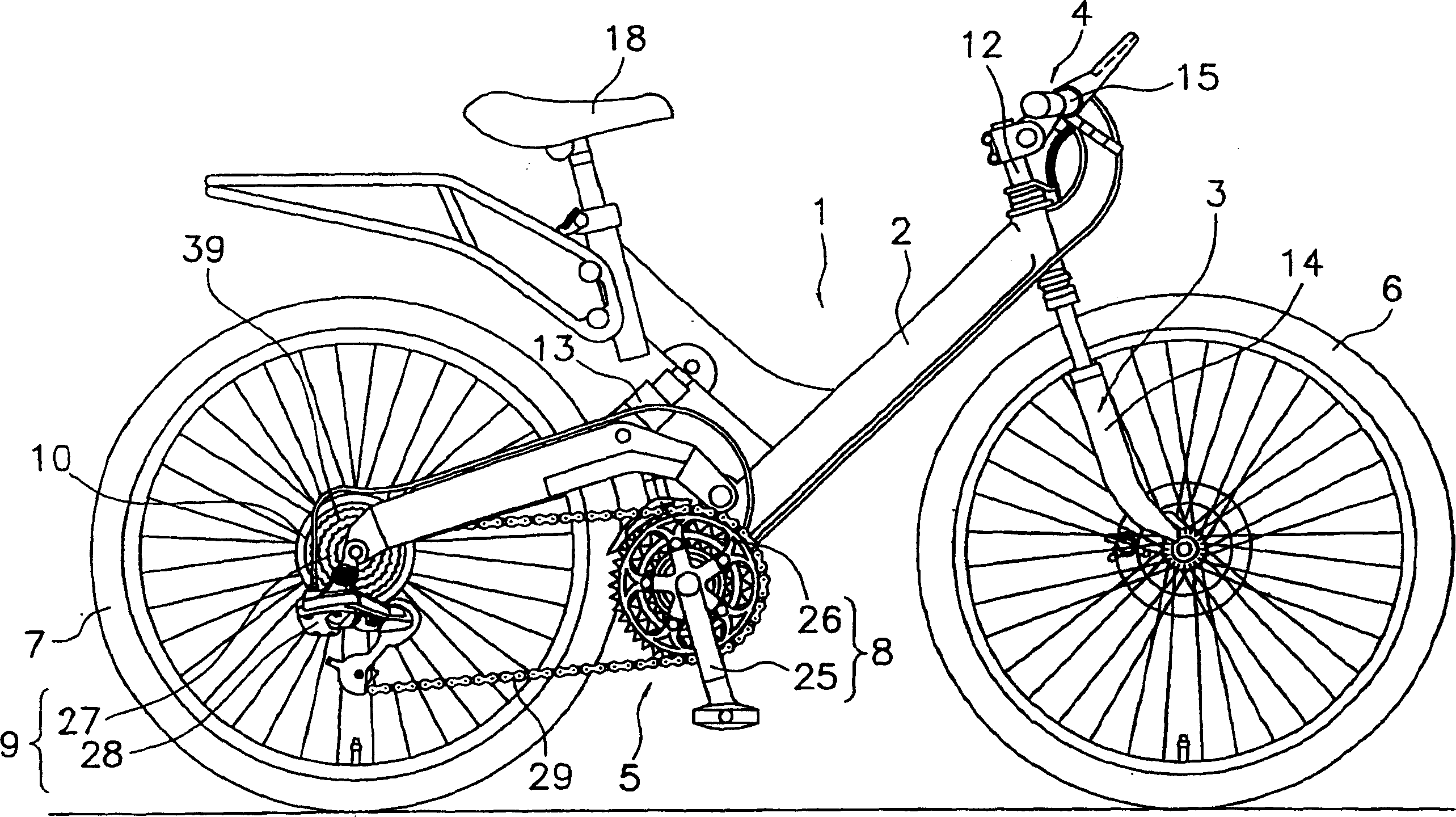
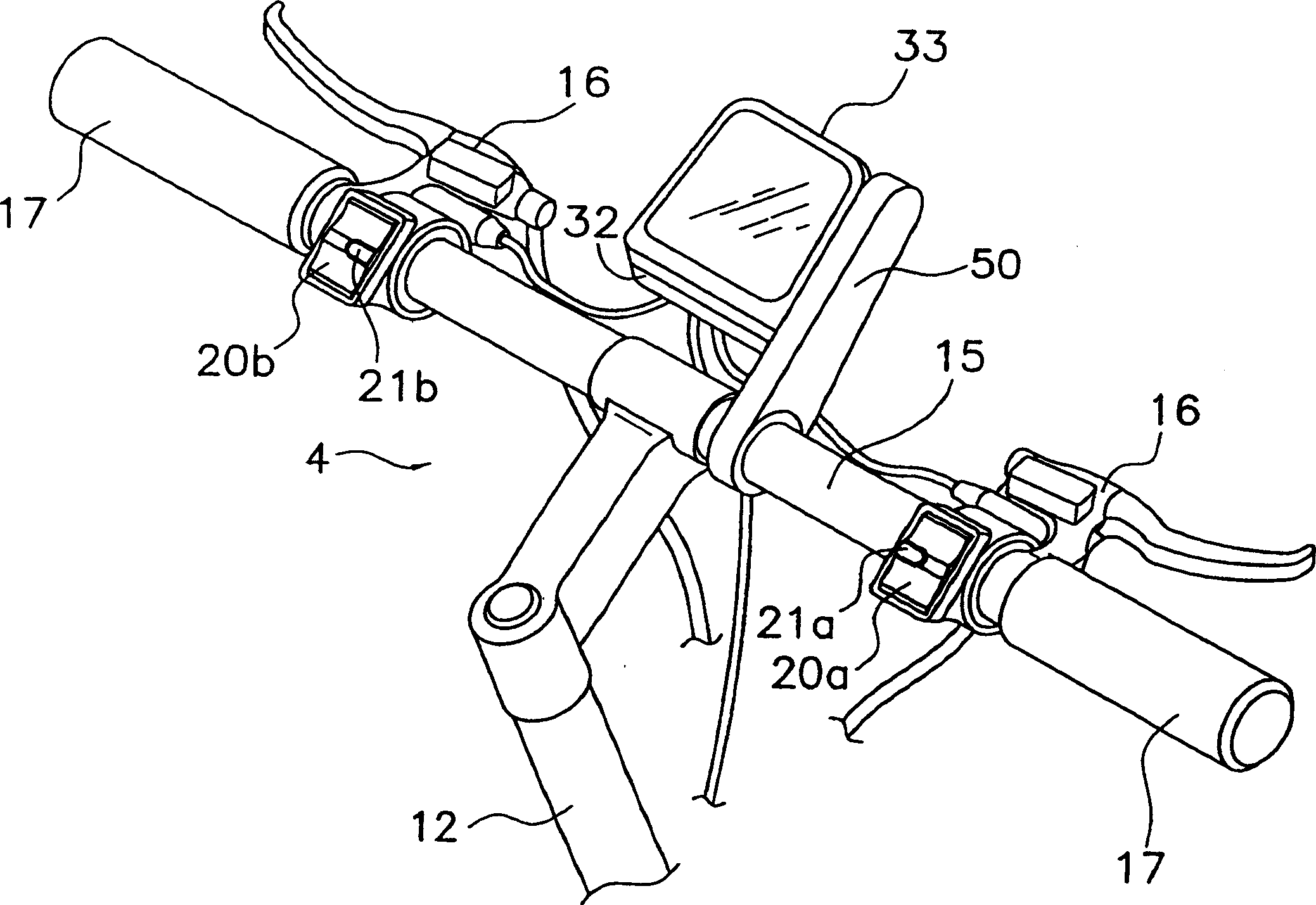
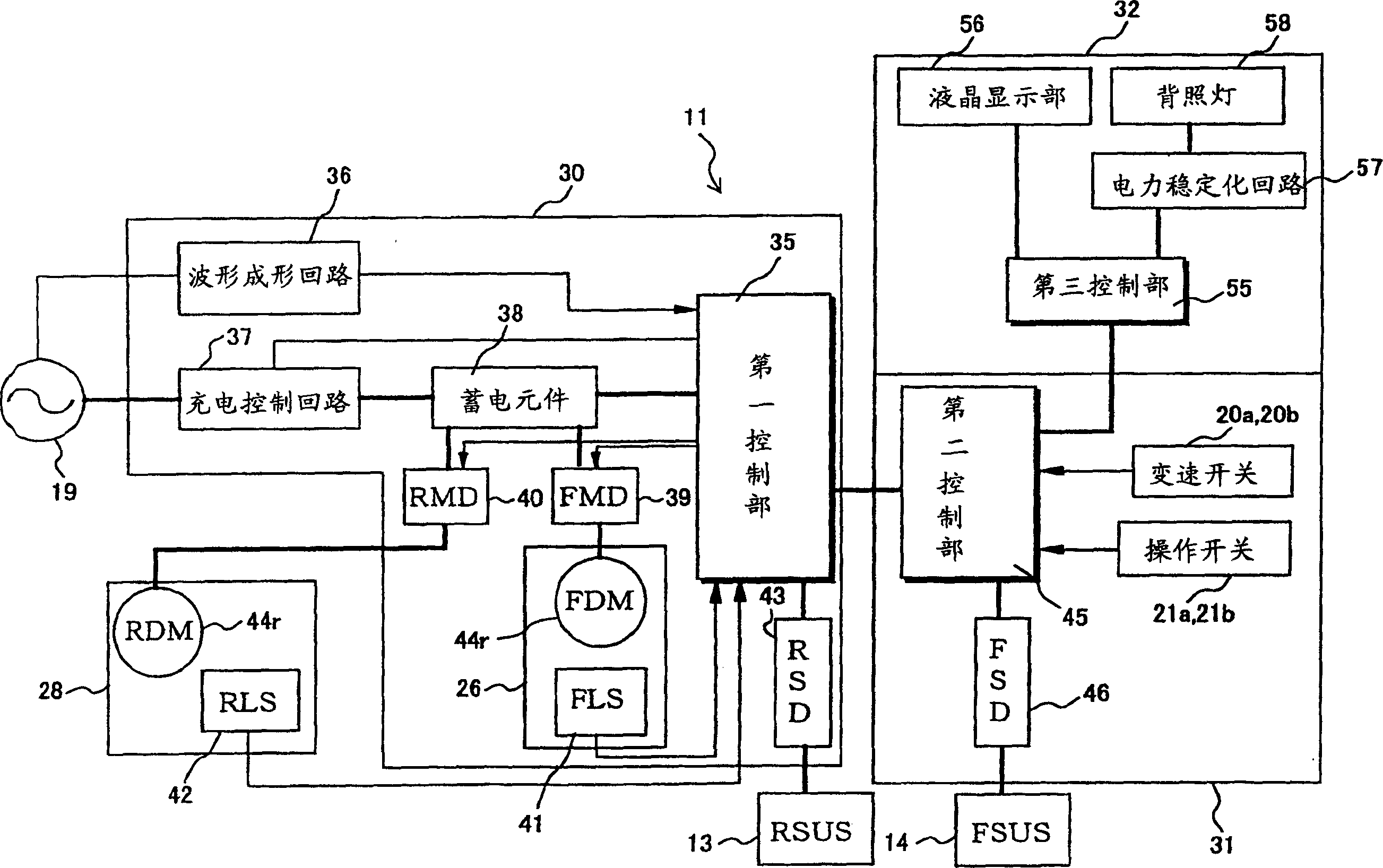
[0041] (a) In the above-mentioned embodiment, the backlight was exemplified as the second electrical component that is not controlled by the control signal, but the second electrical component of the present invention is not limited to the backlight. All electrical components for bicycles that operate electrically, such as headlights or taillights.

[0042] (b) In the above-mentioned embodiment, the alternator was exemplified as the power source, but the power source may be a DC power source including a primary cell or a storage battery.

[0043] (c) In the above embodiment, the hub dynamo mounted on the rear wheel was exemplified, but a hub dynamo mounted on the front wheel or a rim dynamo that contacts the rim to generate electricity may be used as the power source.


PUM


Abstract

A bicycle electrical control circuit provides power and control signals to a plurality of bicycle components. The circuit comprises a power circuit that provides a power signal for the plurality of bicycle components, a control circuit that provides a control signal that controls at least one of the plurality of bicycle components, and a power stabilizing circuit (57) coupled to the power circuit. The power stabilizing circuit (57) stabilizes power provided from the power signal to at least one of the plurality of bicycle components.

Description

technical field [0001] The present invention relates to a driving device, in particular to a driving device for bicycle electrical components mounted on a bicycle to drive electrical components operated by electric power supplied from a power source. Background technique [0002] In recent years, various electrical components have been mounted on bicycles. For example, bicycles are equipped with electric components such as a so-called cycler computer that indicates the running state of the bicycle, or a control unit with a built-in shift computer for automatically shifting the speed changer. [0003] Conventionally, electric power has been supplied to such electrical components from batteries such as primary cells and storage batteries. When the number of electrical components increases, since the power supply is common, it is necessary to use power lines to connect from the power supply to multiple electrical components. transmission signal line. [0004] In the case of ...

Claims


Application Information

Patent Timeline
Patent Type & Authority Applications(China)
IPC IPC(8): B62J99/00B62J6/00B62J6/04B62J6/12B62M25/08
CPCB62J6/003B62M25/08B62J6/015
Inventor 大原弘嗣
Owner SHIMANO INC
Learn More