Noise filter

A noise filter and medium technology, applied to waveguide devices, inductors, fixed inductors, etc., can solve the problem of difficult signal attenuation ratio setting separately, and achieve the effect of increased transmission loss, reduced impact, and easy matching

Inactive Publication Date: 2004-03-31
MURATA MFG CO LTD
View PDF0 Cites 9 Cited by
  • Summary
  • Abstract
  • Description
  • Claims
  • Application Information

AI Technical Summary

Problems solved by technology

There is a problem that it is difficult to set the signal attenuation ratio of each mode separately

Method used


Image

  • Noise filter
  • Noise filter
  • Noise filter

Examples


Embodiment Construction

[0072] A noise filter according to an embodiment of the present invention will be described in detail below with reference to the drawings.

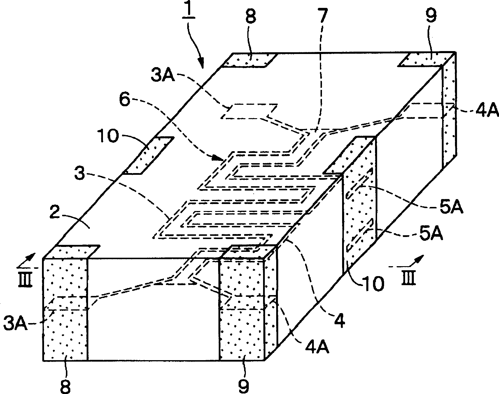
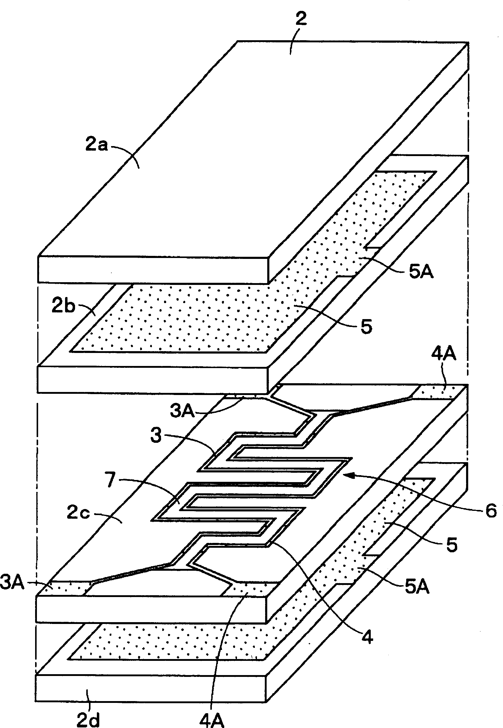
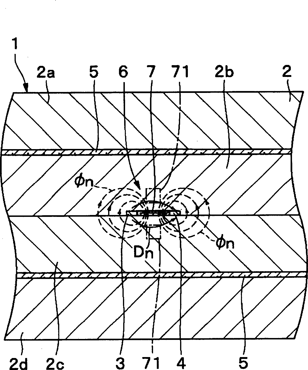
[0073] Figure 1 to Figure 9 Indicates the first embodiment of the present invention, 1 is a noise filter in this embodiment, and the noise filter is generally composed of magnetic layers 2a to 2d described later, signal lines 3 and 4, ground electrodes 5, and dielectric members 7. It is composed of electrode terminals 8 and 9 for signal and electrode terminal 10 for grounding.

[0074] 2 is a laminated body as an insulating medium, and the laminated body 2 is approximately prism-shaped and constitutes the outer shape of the noise filter 1 . Furthermore, the laminated body 2 is composed of four insulating layers of magnetic bodies 2a to 2d, and is formed, for example, by pressing and sintering in a state where four magnetic body plates are stacked one on another. Furthermore, the magnetic layers 2a to 2d are formed in a substantially q...


PUM


Abstract

Four magnetic layers consisting of upper and lower magnetic layers and intermediate magnetic layers are laminated to form a laminated unit. Two signal lines are disposed side by side between the intermediate magnetic layers, and two ground electrodes sandwich the intermediate magnetic layers therebetween so as to form a transmission line. A dielectric member is disposed between the two signal lines. With this configuration, a common-mode signal is attenuated by utilizing magnetic loss in the magnetic layers. In contrast, by providing the dielectric member, a normal-mode signal is allowed to propagate by reducing the effective relative magnetic permeability while preventing the occurrence of blunt waves.

Description

technical field [0001] The present invention relates to a noise filter suitable for an electronic circuit utilizing a differential signal such as a high-speed differential interface. Background technique [0002] Generally, an electronic circuit using a differential signal (normal mode signal) is constituted by a differential circuit composed of two circuits. As described above, in this differential circuit, common mode noise (common mode signal) that causes radiated electromagnetic noise is generated due to various reasons. Therefore, a common mode choke coil as a noise filter is connected in the middle of the differential circuit, and common mode noise is removed by reflecting the common mode signal while passing the normal mode signal. [0003] However, in the conventional technology described above, since noise is suppressed by reflection loss, for example, when a noise filter is installed in a circuit connecting the circuits, there is a possibility that noise with a sp...

Claims


Application Information

Patent Timeline
Patent Type & Authority Applications(China)
IPC IPC(8): H03H7/06H01P1/203H03H1/00H03H7/075H03H7/09
CPCH03H1/0007H01P1/23H01P1/20345H01P1/227H03H2001/0085H01P1/203
Inventor 原田徹
Owner MURATA MFG CO LTD
Why Eureka
Try Eureka