Front Lamp for vehicle

A technology of headlights and vehicles, applied in the direction of vehicle lighting systems, headlights, vehicle components, etc.

Inactive Publication Date: 2004-04-07
KOITO MFG CO LTD
View PDF2 Cites 20 Cited by
  • Summary
  • Abstract
  • Description
  • Claims
  • Application Information

AI Technical Summary

Problems solved by technology

[0010] That is, as described in "Patent Document 1", if only a plurality of identical lamp units are used, the pattern shape and light intensity distribution of the illumination pattern formed by the illumination of each lamp unit are the same, so there is the following problem , that is, the obtained illumination pattern of the vehicle headlamp as its synthetic illumination pattern cannot be formed into the desired pattern shape and illumination intensity distribution

Method used


Image

  • Front Lamp for vehicle
  • Front Lamp for vehicle
  • Front Lamp for vehicle

Examples


Embodiment Construction

[0037] Embodiments of the present invention will be described below using the drawings.

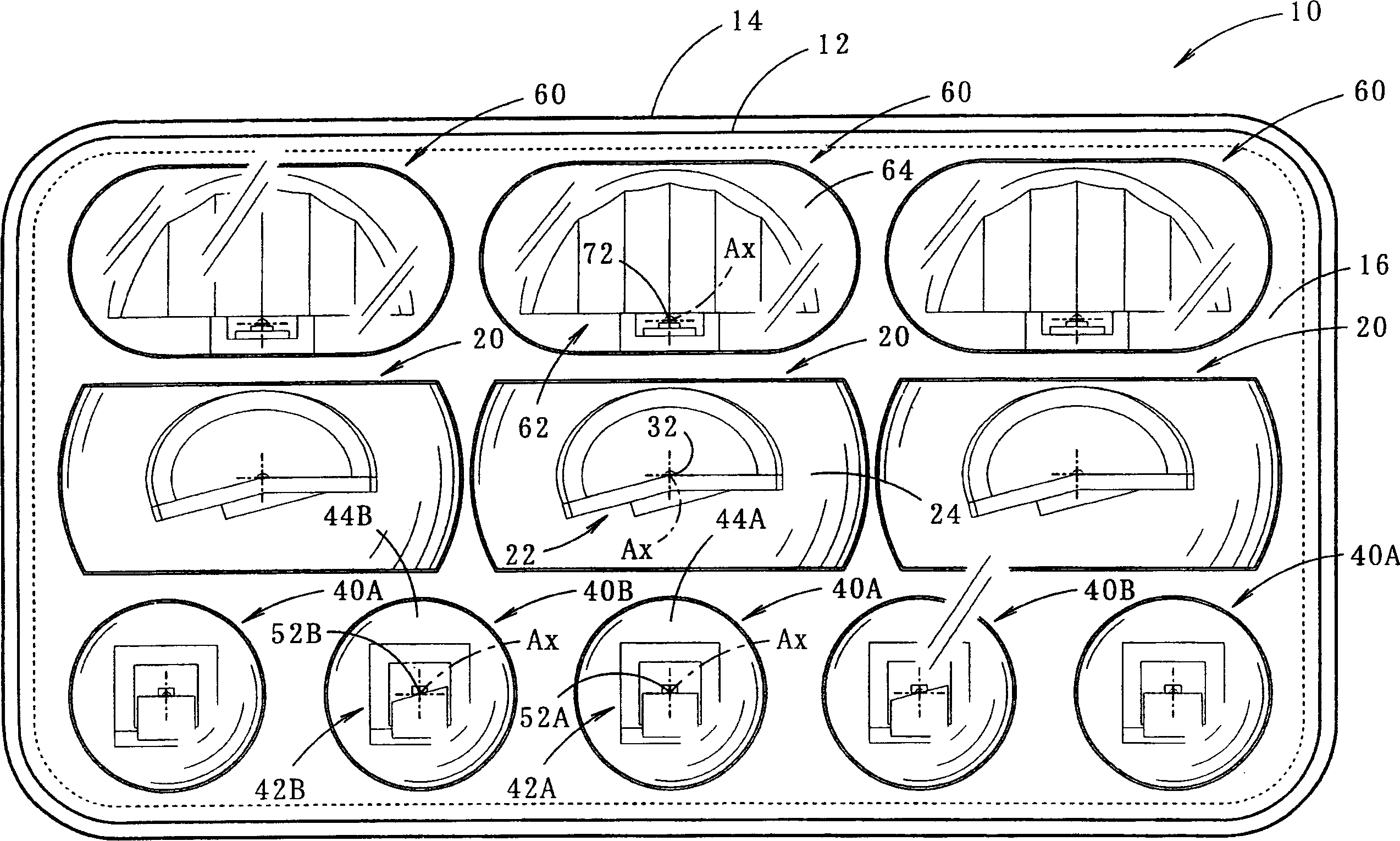
[0038] figure 1 It is a front view showing a vehicle headlamp 10 according to an embodiment of the present invention

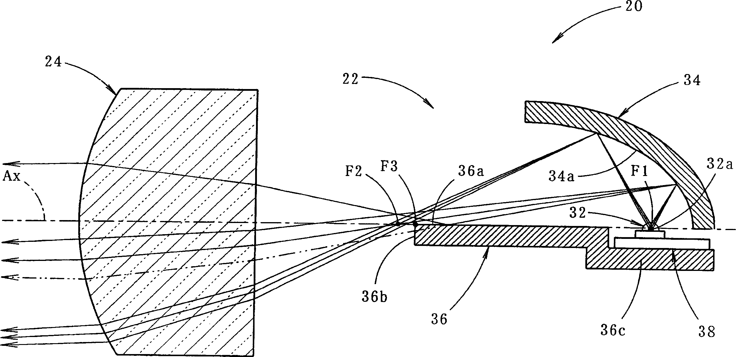
[0039] This vehicle headlamp 10 is a headlamp for low beams. In an interior lamp formed by a transparent light-transmitting cover 12 and a lamp body 14, 11 lamp units 20, 40A, 40B, and 60 are covered in three stages above and below. containment.

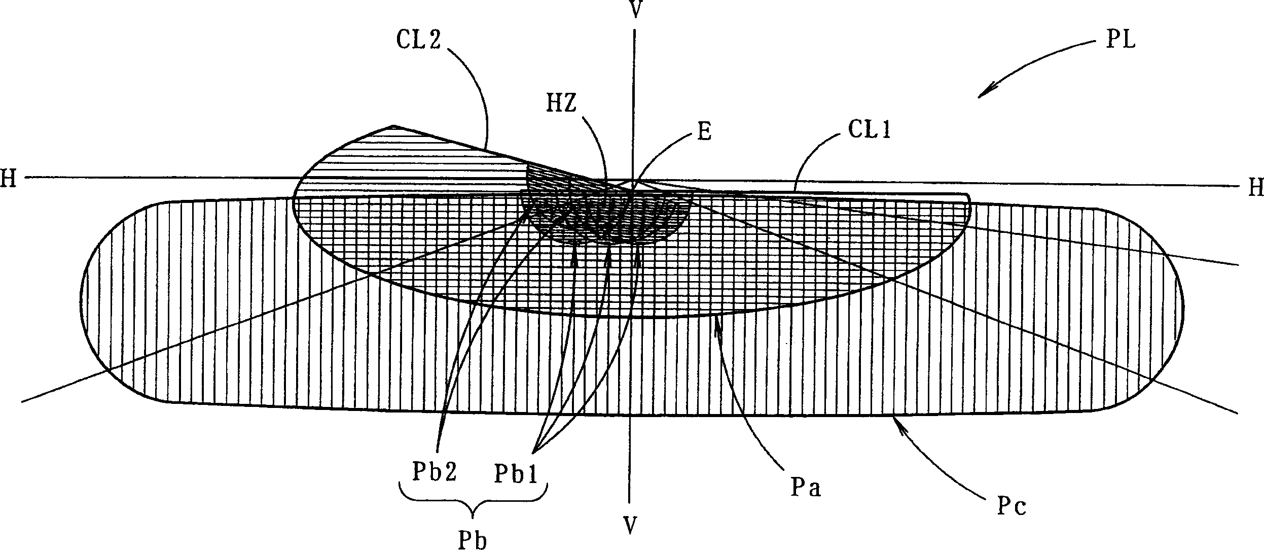
[0040] figure 2 It is a perspective view of a low beam illumination pattern PL formed on a virtual vertical screen arranged at a position 25 mm in front of the lamp by the illumination of the vehicle headlamp 10 described above.

[0041] The illumination pattern PL for low beam is a left illumination pattern having horizontal and inclined cutting lines CL1 and CL2 at the upper edge thereof. The position of the inflection point E, which is the focus of the two cutting lines, is set at about 0.5 to 0.6° below the vanishing po...


PUM


Abstract

The headlamp has multiple lamp units (20,40A,40B,60) each using light-emitting diodes (LED) as light sources. One type of lamp unit (20) uses a reflector and a lens to produce a convergent beam combining direct and reflected light, another type (40A,40B) uses a convergent lens to produce direct illumination, and the third type (60) delivers only reflected light.

Description

technical field [0001] The present invention relates to a vehicle headlamp configured to form a predetermined illumination pattern. Background technique [0002] Conventional signal lamps for vehicles such as tail lamps often use light-emitting diodes as their light sources. For example, "Patent Document 1" describes a vehicle signal lamp in which a plurality of lamp units having light emitting diodes as light sources are arranged. [0003] Also, "Patent Document 2" describes a lamp that forms a desired illumination pattern in a vehicle headlamp by selectively lighting some of a plurality of light emitting diodes arranged in a matrix. [0004] 【Patent Document 1】 [0005] Japanese Patent Application Publication No. 2002-50214 [0006] 【Patent Document 2】 [0007] Japanese Patent Application Publication No. 2001-266620 [0008] In the lamp structure described in "Patent Document 2", the shape of the illumination pattern can be changed by separating the lighting and non-l...

Claims


Application Information

Patent Timeline
Patent Type & Authority Applications(China)
IPC IPC(8): F21S8/12B60Q1/04F21S8/10F21V7/00F21V13/00F21W101/10F21Y101/02
CPCY10S362/80F21S48/1163F21S48/137F21S48/1159F21Y2101/02B60Q1/04F21S48/1154F21Y2115/10F21S41/143F21S41/148F21S41/153F21S41/155F21S41/336F21S41/20F21S41/32F21W2102/00
Inventor 达川正士石田裕之佐塚清
Owner KOITO MFG CO LTD
Why Eureka
Try Eureka