Hollow plate

A hollow and planar technology, applied to hollow objects, building components, household components, etc., can solve the problems of increased thickness of hollow boards, increased costs, and increased number of components

Inactive Publication Date: 2004-05-05
YAMAHA CORP
View PDF0 Cites 5 Cited by
  • Summary
  • Abstract
  • Description
  • Claims
  • Application Information

AI Technical Summary

Problems solved by technology

[0003] Since the structure of the hollow plate disclosed in JP-A-7-214712 is such that the cross-sectional area of ​​the hollow portion is differentiated by using two corrugated plates, one of the disadvantages is that the overall thickness of the hollow plate increases, and another disadvantage is that the components The increase in the number inevitably increases the cost of the burden, and the necessity to join the corrugated plates together also leads to an increase in the number of assembly steps

Method used


Image

  • Hollow plate
  • Hollow plate
  • Hollow plate

Examples


no. 1 example

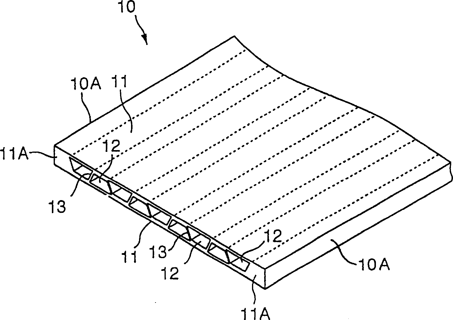
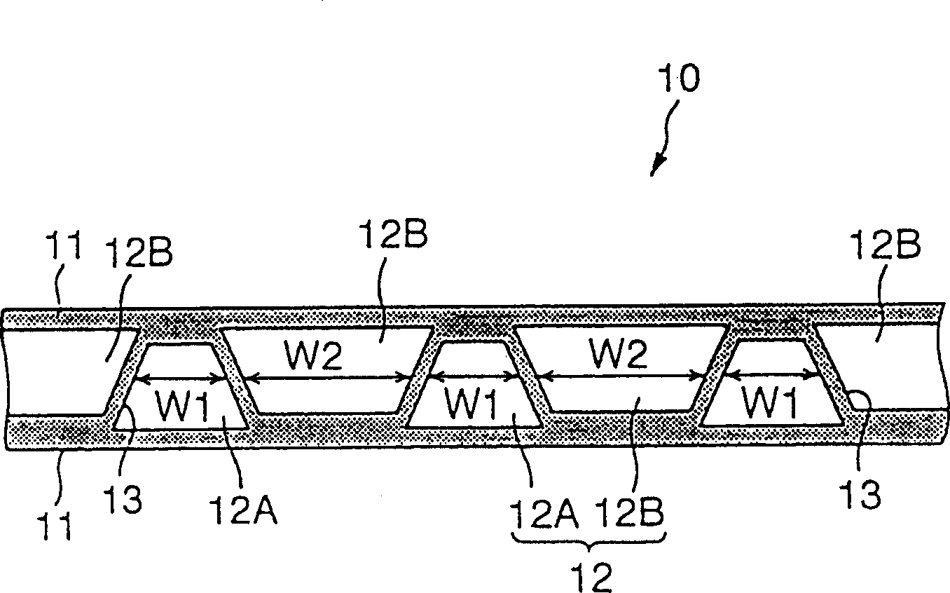
[0041] figure 1 is a schematic perspective view of a hollow panel according to the first embodiment, figure 2 It is an end view of a part of the hollow plate. Referring to the accompanying drawings, a hollow panel 10 that can be used as a building material, such as wall panels, floors, and ceilings, includes: a pair of straight outer surfaces 11, which are substantially parallel to each other, and a plurality of hollow parts 12, which are placed on the Between the outer surfaces 11, they are arranged on substantially the same plane.

[0042] The shape of each hollow portion 12 is along the figure 2 Stretches linearly in the direction of the paper plane where it resides. The hollow portion 12 is formed so that the partition walls 13 arranged at predetermined intervals in the lateral direction in the figure are inclined at approximately the same angle, and in alternately different directions. As a result, each hollow portion 12 is approximately trapezoidal in shape. In th...

no. 2 example

[0047] Figure 4 It is the second embodiment of the present invention. This embodiment is characterized in that, although the hollow parts 12 have the same cross-sectional area, different thicknesses T1 and T2 of the partition walls 13 between these hollow parts 12 are present alternately. The thickness is set to satisfy the relationship: T1>T2.

[0048] Also in the second embodiment, the area of ​​thickness T1 has higher surface density or rigidity than the area of ​​thickness T2. Therefore, this embodiment has a structure in which the resonant frequency of the panel is not uniform on the plane of the hollow panel 10, and has the same sound insulation effect as the first embodiment.

no. 3 example

[0050] Figure 5 with 6 It is the third embodiment of the present invention. This embodiment is characterized in that a solid portion 15 is formed in a specific area of ​​the initially formed hollow portion. Such as Image 6 As shown, the solid portion 15 may be formed linearly in an area corresponding to a single hollow portion, or alternatively formed by extending to a plurality of hollow portions 12 . In the example shown, the solid portion 15 extends linearly. However, the way it stretches is not limited to the linear one. It can be said that this embodiment is realized by increasing the thickness of a specific partition wall 13 .

[0051] Also, this embodiment has the same effect as the previous embodiment.


PUM


Abstract

A hollow panel (10) includes comprise hollow portions (12) between front and rear outer sides having a substantially flat plate shape. In the hollow panel (10), the surface density is partially differentiated, whereby a lack of sound insulation due to the coincidence effect at a specific frequency is prevented from occurring. The surface density or the rigidity can be made non-uniform to suppress the lack of sound insulation, by differentiating sectional areas by forming plural kinds of widths of the hollow portions (12), or by differentiating the distances between partition walls (13) or the thicknesses of the walls.

Description

technical field [0001] The invention relates to a hollow board, especially a hollow board suitable for building materials, such as wall materials, floor materials and ceiling materials. Background technique [0002] Conventionally, a hollow panel having a hollow portion is used for various building panels. In such a hollow panel, it is possible to achieve heat retention and weight reduction. In a known hollow plate, two corrugated plates with corrugated end faces are sandwiched between two flat plates as surfaces to form a plate, and the hollow portion corresponding to the corrugation is expanded laterally (for example, see JP-A-7-214712). This JP-A-7-214712 discloses a hollow panel configured to stack two corrugated panels back-to-back such that the protruding portions of the panels abut each other and are sandwiched in the flat panels. Therefore, in the complete state of such panels, hollow parts with different cross-sectional areas are incorporated inside, so that the ...

Claims


Application Information

Patent Timeline
Patent Type & Authority Applications(China)
IPC IPC(8): E04B1/84E04B1/86E04B2/02E04C2/30E04C2/34E04C2/36
CPCE04B1/86E04B2001/8471E04C2/36E04B2001/8457E04B2001/8476E04C2/34
Inventor 棚瀬廉人小林哲
Owner YAMAHA CORP
Why Eureka
Try Eureka