Injectio moulding machine control method for reducing weight change of moulded product

A technology of injection molding machine and algorithm, which is applied in the field of control to reduce the weight change of molded products, and can solve problems such as difficulty

Inactive Publication Date: 2004-05-12
SUMITOMO HEAVY IND LTD
View PDF0 Cites 0 Cited by
  • Summary
  • Abstract
  • Description
  • Claims
  • Application Information

AI Technical Summary

Problems solved by technology

Changing the number of revolutions of the screw or the back pressure of the screw can be considered as another method, but it is not easy to use this method because it has a great influence on the temperature of the resin

Method used


Image

  • Injectio moulding machine control method for reducing weight change of moulded product
  • Injectio moulding machine control method for reducing weight change of moulded product
  • Injectio moulding machine control method for reducing weight change of moulded product

Examples


Embodiment Construction

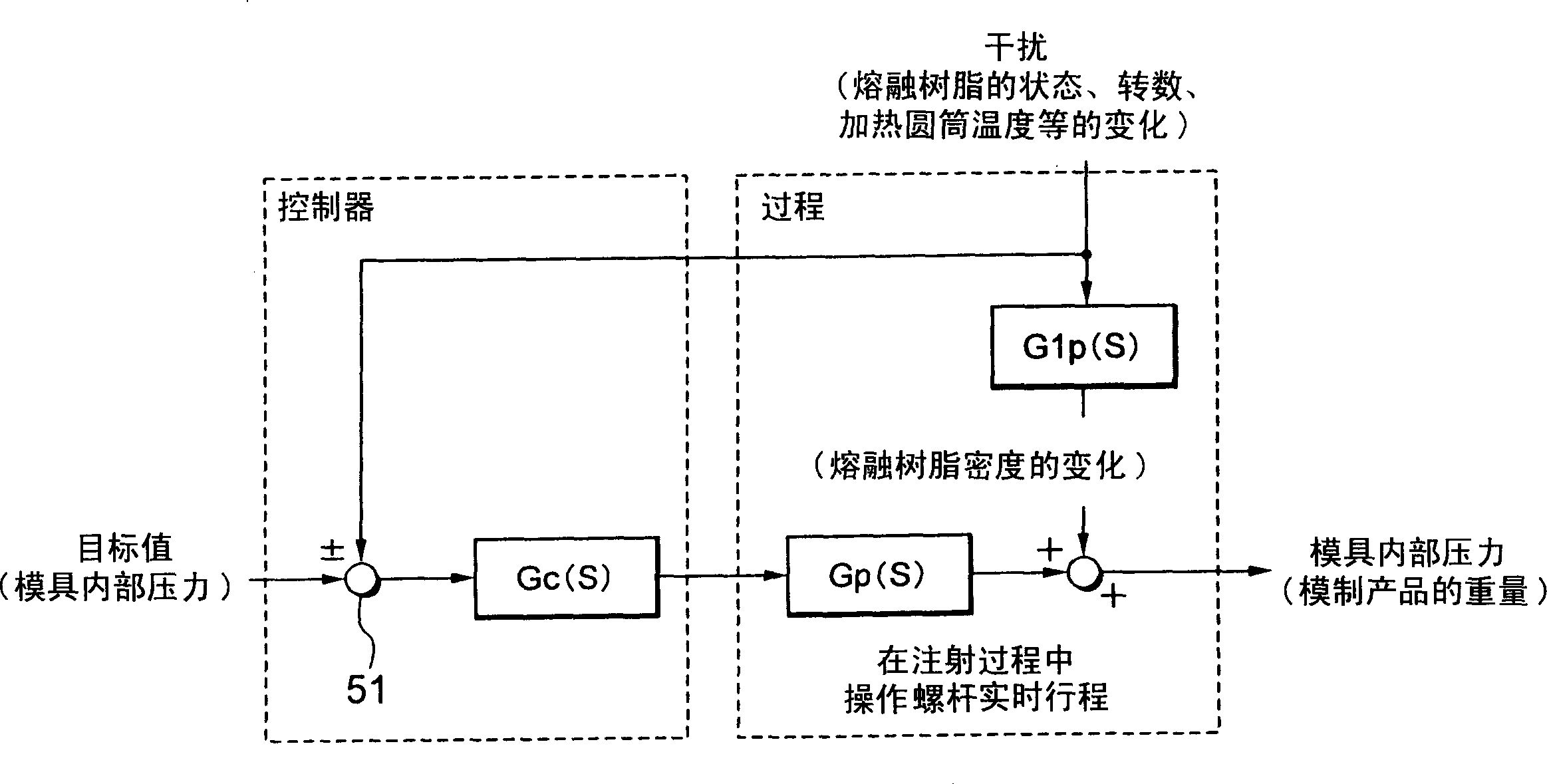
[0028] refer to Figure 4 , the mold internal pressure feed-forward control system of the first embodiment of the present invention will be described below. Figure 4 It is a block diagram of the mold internal pressure feed-forward control system of the present invention. In the present invention, as Figure 4 As shown, a feedback control system 60 is added to combine image 3 described in the feed-forward control system.

[0029] The feedback control system 60 is used to feed back the change of the molten resin measured by the measuring device for measuring the density of the molten resin. The feedback control system 60 operates during the injection molding process and is designed to eliminate the uncertain effects found in conventional systems by minimizing changes in the density of the molten resin by the feedback control system 60 before the injection process begins.

[0030] More specifically, he said that in the feedback control system 60, any one of the number of re...


PUM


Abstract

A control method for an injection molding machine comprises the steps of measuring a density of a molten resin in a heating cylinder, determining a stade of the temperature of the heating cylinder based upon predetermined algorithm and controlling the temperature of the heating cylinder based upon the measuring step and the determined state of the temperature, thereby minimizing variations in density of the molten resin.

Description

technical field [0001] The present invention relates to a method of controlling an injection molding machine, and more particularly to a control method suitable for reducing weight variations of molded products. Background technique [0002] Referring to Fig. 1, the motor-driven injection molding machine will be described below, focusing on the injection device therein. Motor-driven injection molding machines consist of an injection unit driven by a servo motor. In this injection unit, the rotation of the servo motor is converted into linear motion through a ball screw and screw nut, which moves the screw back and forth. [0003] In FIG. 1 , the rotation of the injection servo motor 11 is transmitted to the ball screw 12 . The screw nut 13 is fixed on the pressure plate 14 and can move back and forth with the rotation of the ball screw 12 . The pressure plate 14 moves along four guide rods 15, 16 (only two are marked in the figure) fixed on the base frame (not marked in t...

Claims


Application Information

Patent Timeline
Patent Type & Authority Applications(China)
IPC IPC(8): B29C45/76B29C45/78
CPCB29C2945/76665B29C2945/76531B29C2945/76287B29C2945/76662B29C2945/76127B29C2945/76066B29C45/78B29C2945/76605B29C2945/76785B29C45/76B29C2945/76083B29C2945/7619B29C2945/76498B29K2995/0063B29C2945/7604
Inventor 数面博义
Owner SUMITOMO HEAVY IND LTD
Why Eureka
Try Eureka