OHC overhead camshaft internal combustion enjine

A technology for camshafts and internal combustion engines, which is applied to valve devices, mechanical equipment, valve drive devices, etc., can solve problems such as trouble, and achieve the effect of firm fixation

Inactive Publication Date: 2004-05-12
HONDA MOTOR CO LTD
View PDF0 Cites 5 Cited by
  • Summary
  • Abstract
  • Description
  • Claims
  • Application Information

AI Technical Summary

Problems solved by technology

In order to form a bearing support portion on the joint surface of such separately manufactured parts, it is necessary to assemble the joint surface at one time, pass through it, process the bearing support portion, and then separate it. This is a troublesome process.

Method used


Image

  • OHC overhead camshaft internal combustion enjine
  • OHC overhead camshaft internal combustion enjine
  • OHC overhead camshaft internal combustion enjine

Examples


Embodiment Construction

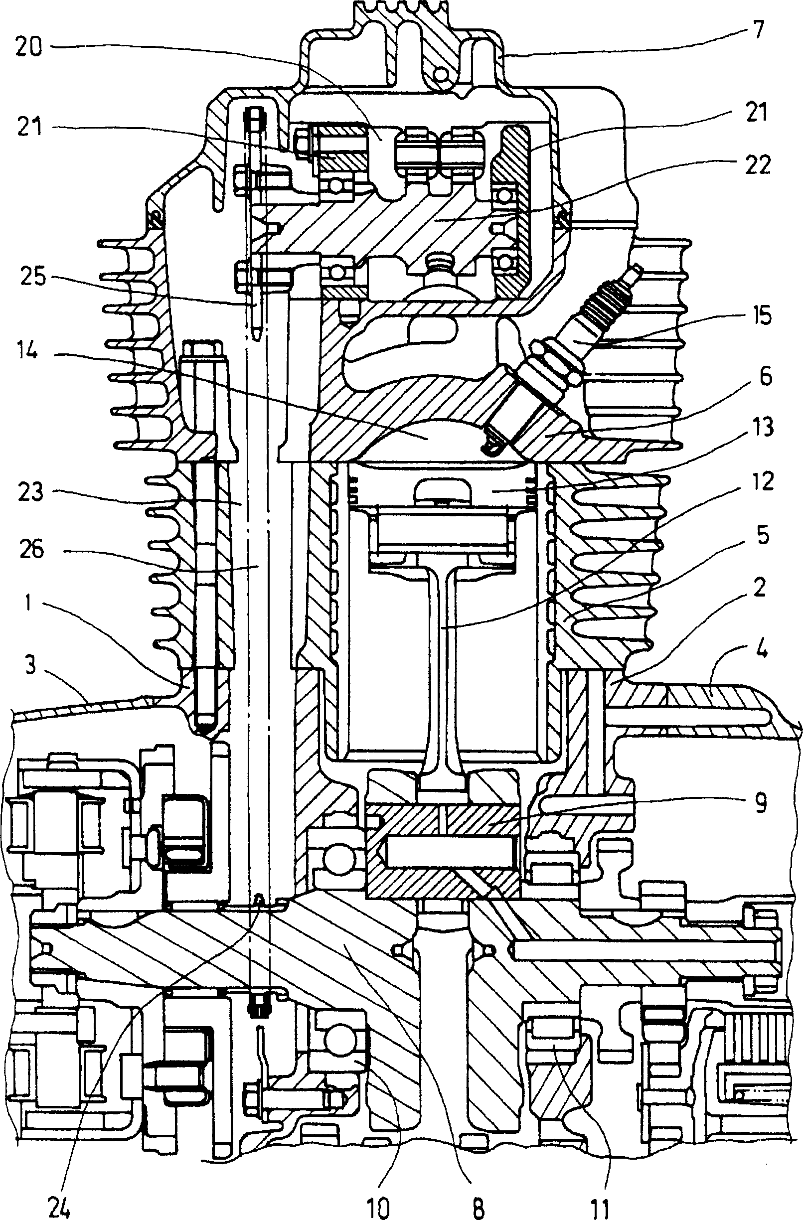
[0022] figure 1 It is a cross-sectional view of an OHC type single-cylinder internal combustion engine for a two-wheeled motorcycle according to an embodiment of the present invention from behind. The shell of this internal combustion engine among the figure is made of left crankcase 1, right crankcase 2, left crankcase cover 3, right crankcase cover 4, cylinder block 5, cylinder head 6, cylinder head cover 7. The crankshaft 8 is integrally formed of left and right parts with crank pins 9 . The crankshaft 8 is rotatably supported on the left crankcase 1 and the right crankcase 2 via rolling bearings 10 , 11 , respectively. The piston 13 is connected to the crank pin 9 via the connecting rod 12 and moves up and down in the cylinder block 5 . A combustion chamber 14 is formed under the cylinder head 6 . The ignition spark plug 15 is mounted on the cylinder head 6 with its front end facing the combustion chamber 14 .

[0023] A camshaft 22 of the valve drive is mounted rotata...


PUM


Abstract

To improve conventional structure that takes a lot of man-hours in manufacture since halved camshaft bearing holding parts are formed by using joint faces of separately produced members such as a cylinder head cover and a cylinder head to facilitate production of a bearing holding part and installation work of a camshaft, in an OHC type internal combustion engine whose rotating camshaft interlocked with a crankshaft is disposed on a cylinder head. A camshaft holder for holding the camshaft to be rotatable is produced separately from the cylinder head or cylinder head cover, and the camshaft holder is tightened together by stud bolts passing through a cylinder.

Description

technical field [0001] The present invention relates to an OHC overhead camshaft type internal combustion engine in which a camshaft is provided on a cylinder head, and more particularly to a structure for supporting the camshaft in a freely rotatable manner. Background technique [0002] In the current camshaft support structure, upper and lower halves of the bearing support portion are formed between the joint surface of the cylinder head cover and the cylinder head, and the camshaft is supported by rolling bearings so that the camshaft can rotate freely (for example, refer to Patent Document 1). [0003] As another camshaft support structure, a camshaft upper support body separate from the cylinder head cover is provided, and upper and lower halves of the bearing support portion are formed between the joint surface of the camshaft upper support body and the cylinder head, and the camshaft is supported by rolling bearings. Can spin freely. The cylinder head cover is mount...

Claims


Application Information

Patent Timeline
Patent Type & Authority Applications(China)
IPC IPC(8): F01L1/04F01L1/02F01L1/047F01L1/06F01L1/18F01L5/18F02F1/24F02F1/42
CPCF01L1/02F01L1/047F01L1/053F01L1/06F01L1/185F01L5/18F02F1/24F02F1/42
Inventor 神户敬司俵田雄一佐藤智康
Owner HONDA MOTOR CO LTD
Why Eureka
Try Eureka