Variable speed device for internal conbustion engine

A speed change device and internal combustion engine technology, applied in the direction of transmission, gear transmission, transmission control, etc., can solve the problems of uncoordinated operators and different shift loads, etc.

Inactive Publication Date: 2004-05-12
HONDA MOTOR CO LTD
View PDF2 Cites 3 Cited by
  • Summary
  • Abstract
  • Description
  • Claims
  • Application Information

AI Technical Summary

Problems solved by technology

Therefore, when performing a gear shifting operation, the shift load is different between upshifting and downshifting, giving the operator a sense of incongruity.

Method used


Image

  • Variable speed device for internal conbustion engine
  • Variable speed device for internal conbustion engine
  • Variable speed device for internal conbustion engine

Examples


Embodiment Construction

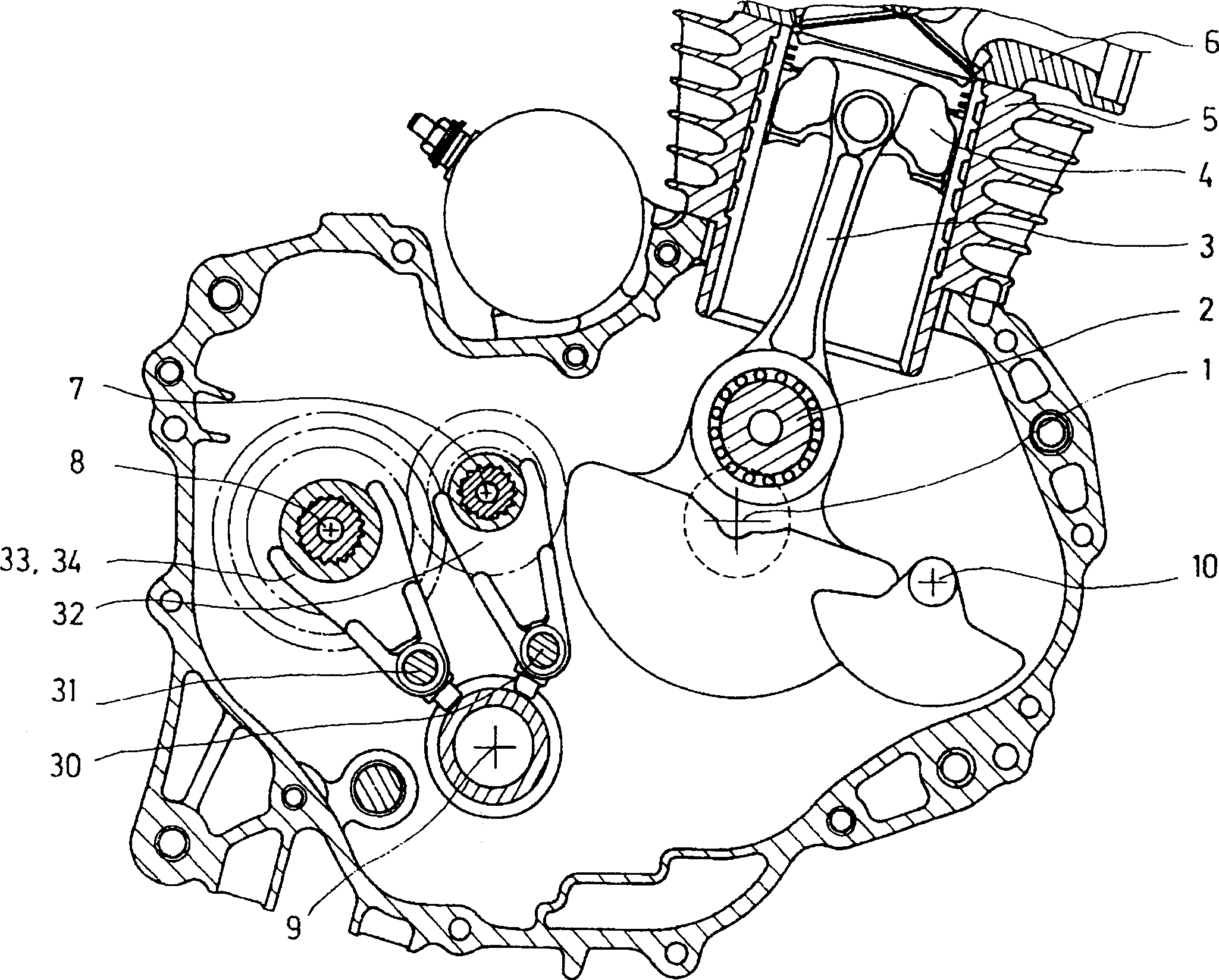
[0031] figure 1 It is a cross-sectional view of the main part of the air-cooled internal combustion engine for motorcycles according to the present invention, viewed from the right side, cut with a front-to-rear surface. In the figure, 1 is a crankshaft, 2 is a crankshaft pin of the crankshaft, 3 is a connecting rod connected with the crankshaft pin 2, and 4 is a piston connected with the connecting rod 3, which moves up and down in the cylinder part 5. A cylinder head 6 is connected to the upper part of the cylinder member 5. 7 is the main shaft of the transmission adjacent to the crankshaft 1, 8 is the secondary shaft of the transmission adjacent to it, 9 is the shift drum, and 10 is the balance shaft .

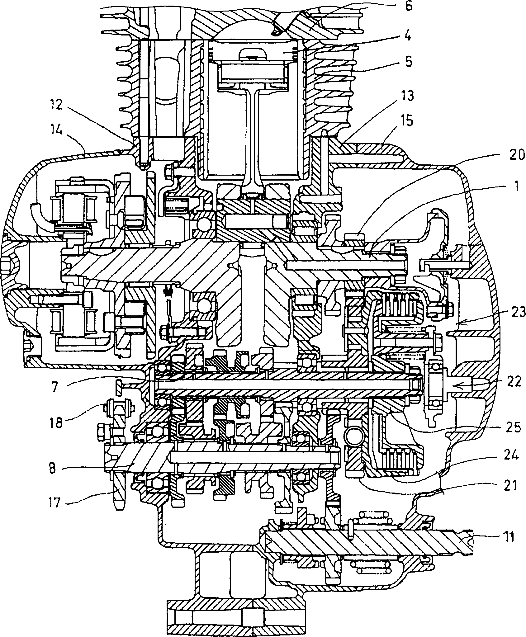
[0032] figure 2 It is a cross-sectional view of the main part of the internal combustion engine as seen from the rear after cutting the main parts of the above-mentioned internal combustion engine through the lateral planes of the piston 4, the crankshaft 1, the main shaft ...


PUM


Abstract

In a variable speed gear change mechanism for an internal combustion engine, gear change operation is performed by rotating a star plate fixed to a shift drum by rotating a change spindle and a stopper roller assembly is pressed against and engaged with a recess on the outer periphery of the star plate. The center of rotation of the aforementioned stopper roller assembly is disposed on a straight line connecting the center of rotation of the aforementioned change spindle and the center of rotation of the aforementioned shift drum, and a pressing force toward the center of rotation of the aforementioned shift drum is exerted on the stopper roller. The usage of a ball bearing at the portion rotatably supporting the shift drum is eliminated by equalizing the load generated during upshifting operation and the load generated during downshifting operation so that the sense of discomfort of the driver is eliminated.

Description

Technical field [0001] The present invention relates to an internal combustion engine transmission device mounted on a vehicle, and more particularly to an internal combustion engine transmission device having a gear-type power transmission device, a shift fork and a shift drum, and the shift drum is rotated by a transmission spindle to perform the transmission. Background technique [0002] In the conventional shift drum transmission, the rotation center of the limit roller of the gear transmission mechanism is not on the extension of the straight line connecting the rotation center of the transmission spindle and the rotation center of the shift fork. Therefore, when the gear shift operation is performed, the shift load is different when shifting the high gear and the low gear, which gives the operator a sense of discomfort. This is obvious when no bearing is used on the rotation support part of the shift drum. In order to eliminate the above-mentioned incompatibility, a ball b...

Claims


Application Information

Patent Timeline
Patent Type & Authority Applications(China)
IPC IPC(8): F16H63/18F16H3/091F16H63/14F16H63/38
CPCF16H63/14F16H63/38F16H63/18F16H3/091F16H57/02F16H63/28
Inventor 神户敬司大关孝东保宽高桥明
Owner HONDA MOTOR CO LTD
Why Eureka
Try Eureka