
Heat absorption tube for solar energy

A technology of heat-absorbing pipes and solar energy, which is applied in the field, can solve problems such as inappropriateness, achieve the effect of reducing heat loss and improving durability

Inactive Publication Date: 2004-05-12
SCHOTT AG
View PDF5 Cites 34 Cited by
  • Summary
  • Abstract
  • Description
  • Claims
  • Application Information

AI Technical Summary

Problems solved by technology

Such collector tubes are simply not suitable for use in parabolic trough collectors

Method used


Image

  • Heat absorption tube for solar energy
  • Heat absorption tube for solar energy
  • Heat absorption tube for solar energy

Examples


Embodiment Construction

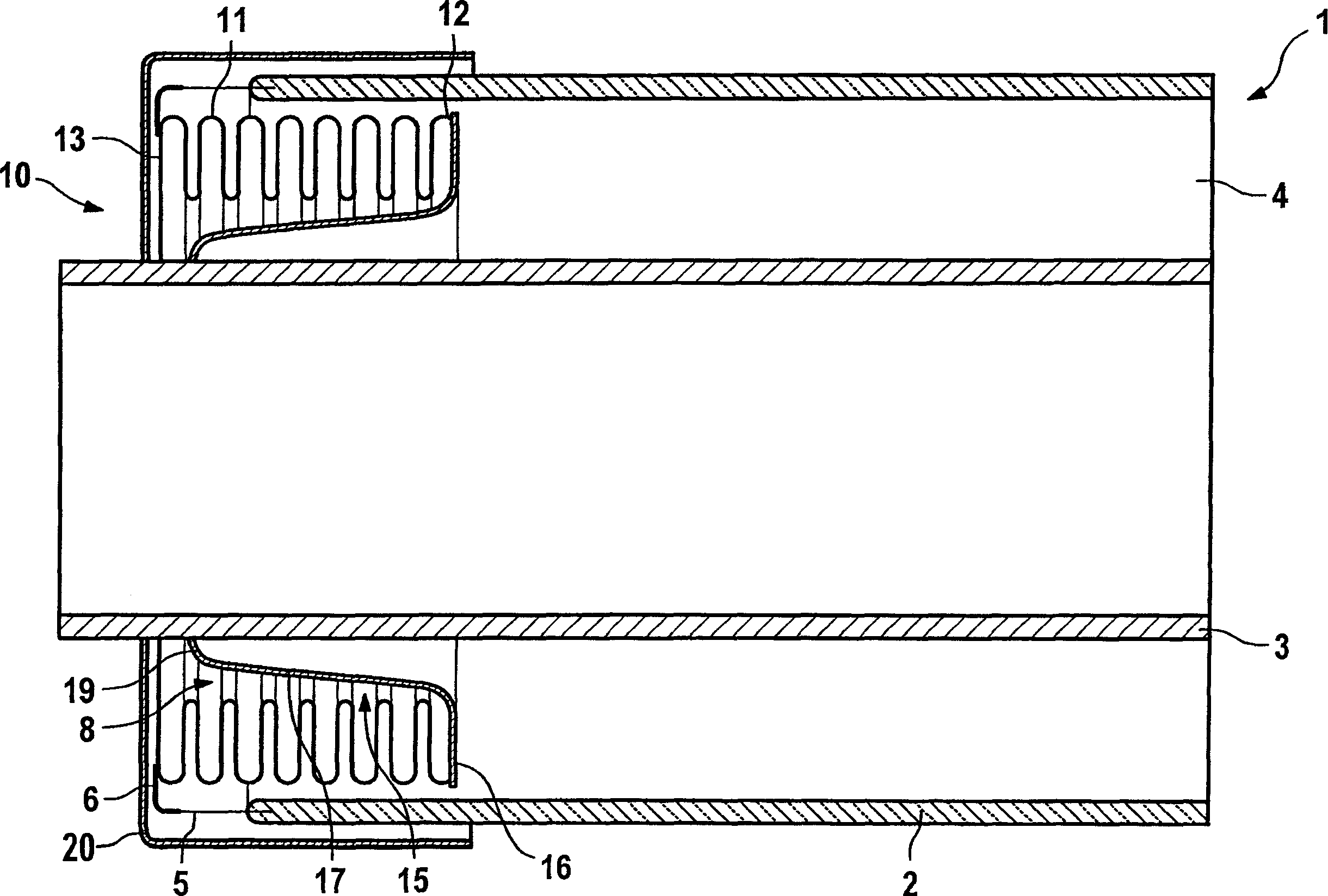
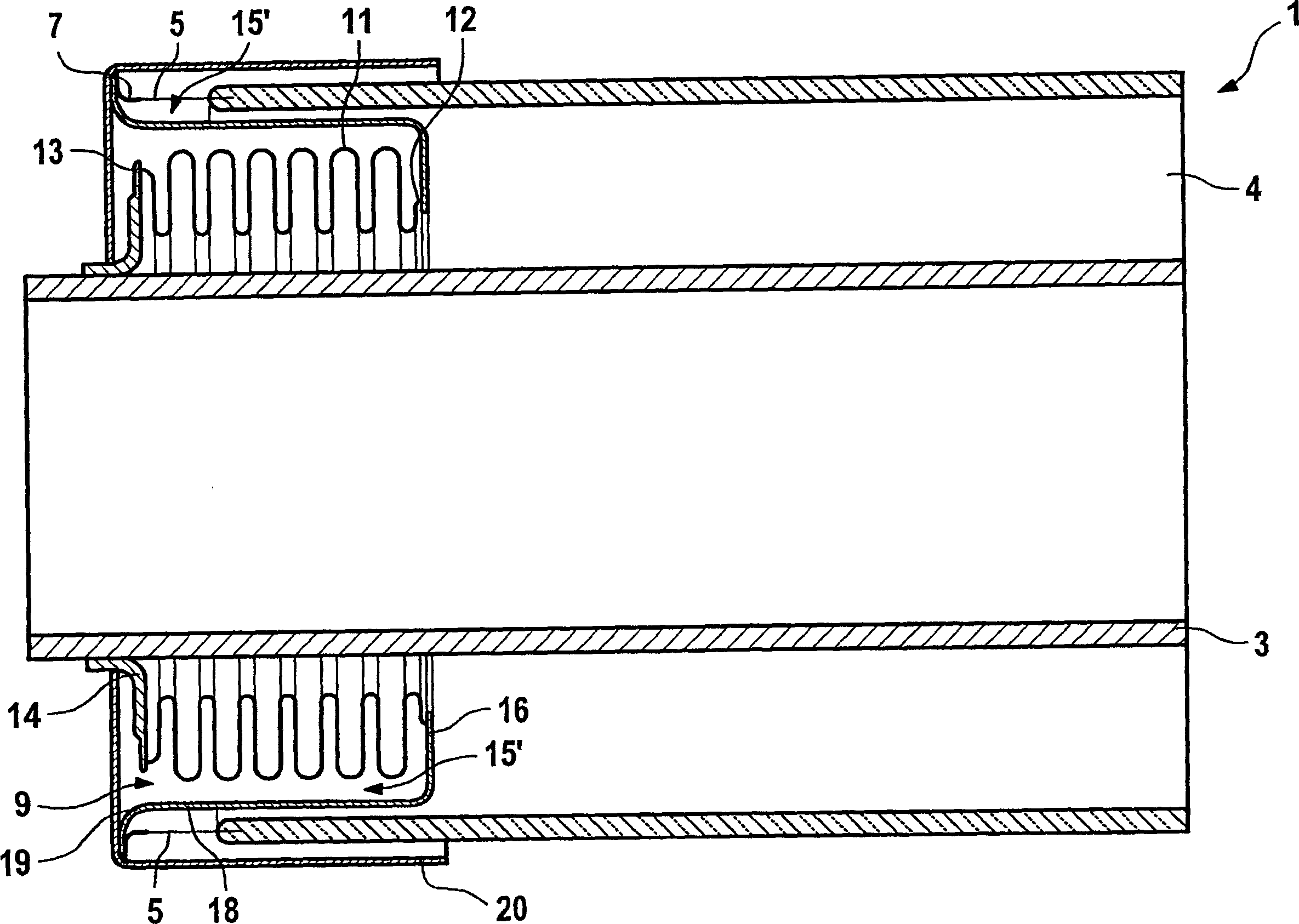
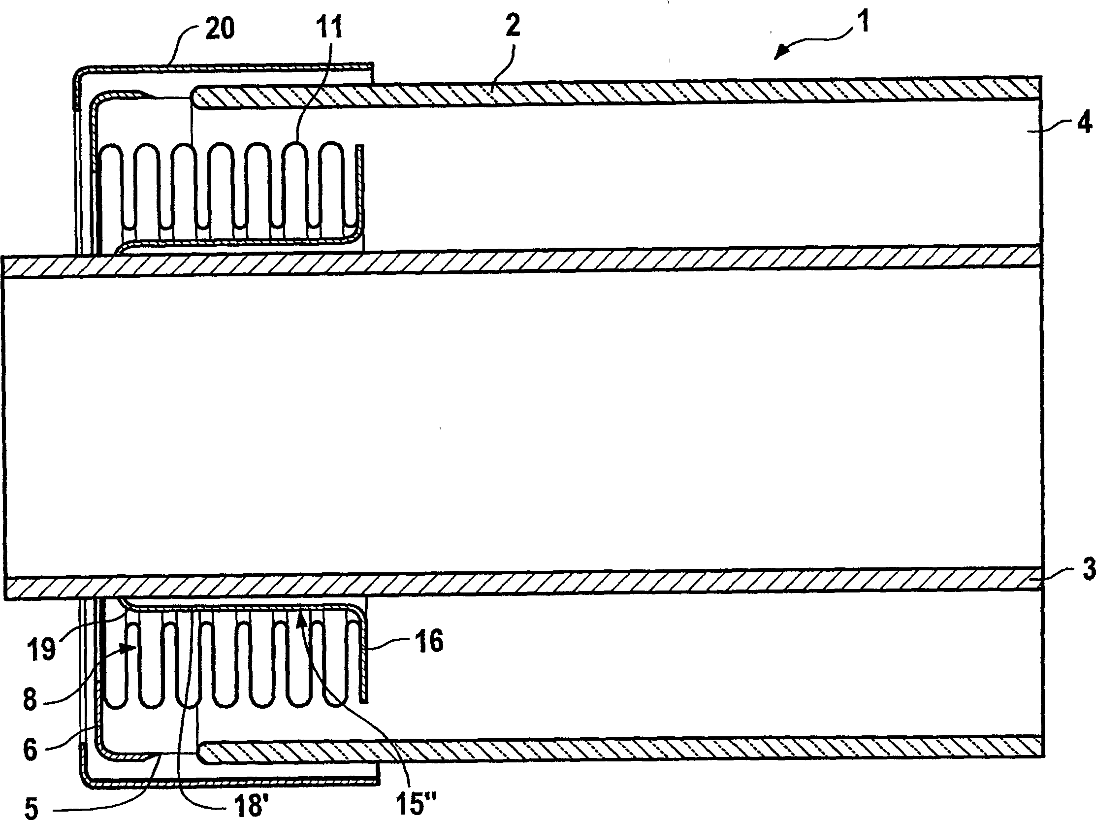
[0039] figure 1 The end of the heat absorber tube 1 is shown in section. The heat absorber tube 1 has a jacket tube 2 made of glass and a metal tube 3 arranged concentrically in the jacket tube 2 , which is coated on the outside with a radiation-selective coating that absorbs solar radiation.

[0040]At the end of the sleeve 2 on the free end side, a glass-to-metal transition piece 5 is fastened, which has a radially inwardly directed band. In the annular space 4 formed between the sleeve 2 and the metal tube 3 , an expansion compensation device 10 in the form of a bellows 11 is arranged, which is fastened with its outer end 13 to the strap 6 of the glass-to-metal transition piece 5 .

[0041] The corrugated tube 11 therefore extends below the glass-to-metal transition piece 5 into the annular space 4 and is fastened at the opposite end to a connecting piece 15 which has an annular disc 16 for this purpose. At its inner edge, the annular disc 16 merges into a conical section...


PUM


Abstract

The absorber pipe (1), especially for a parabolic collector for a solar heat collecting apparatus, is described. The absorber pipe (1) has a central metal pipe (3) and a glass sleeve tube (2). An expansion compensation device (10) is provided, which is arranged at least partially in an annular space (4) between the metal pipe (3) and a glass-metal transitional element (5), which is attached to the sleeve tube (2). The expansion compensation device (10) can have a folding bellows (11). Furthermore a connecting element (15) is provided, which has either a cylindrical or a conical section (17, 18, 18').

Description

technical field [0001] The invention relates to a heat absorber tube, in particular a parabolic trough collector absorber tube for use in a solar thermal power plant, with a central metal tube and a glass sleeve surrounding the central metal tube, at its free end a glass-metal- The transition piece forms an annular space between the metal pipe and the sleeve, wherein the metal pipe and the transition piece are connected to each other displaceably relative to each other in the longitudinal direction by means of at least one expansion compensation device. The invention also relates to the application of the parabolic trough heat collector and the heat absorption pipe. Background technique [0002] For example, the 124th issue of "Journal of Solar Engineering" in May 2002 introduced parabolic trough collectors on page 109. [0003] A glass-to-metal joint is characterized in that it is a direct material joint without additional adhesive material (metal to glass or glass solder=...

Claims


Application Information

Patent Timeline
Patent Type & Authority Applications(China)
IPC IPC(8): F24J2/46F16L27/12F24S10/40F24S10/70F24S20/20
CPCY02E10/44Y02E10/41F24J2002/4681F24J2/055F24J2/07F24J2/4636F24S2025/6013F24S40/80F24S20/20F24S10/45Y02E10/40
Inventor T·库克尔科恩F·-D·德尼茨N·本茨
Owner SCHOTT AG
Learn More