Switch power supply device

A switching power supply and voltage technology, applied in output power conversion devices, electrical components, regulating electrical variables, etc., can solve the problems of unstable output voltage and difficulty in speeding up the comparator driver 65

Inactive Publication Date: 2004-05-19
ROHM CO LTD
View PDF1 Cites 42 Cited by
  • Summary
  • Abstract
  • Description
  • Claims
  • Application Information

AI Technical Summary

Problems solved by technology

However, it is difficult to increase the speed of these comparators 68 and drivers 65
[0013] Moreover, since the passing or blocking of the PWM signal is controlled by the comparison output of the comparator 68, there is also the problem that the output voltage is easily unstable due to the switching action during current limitation.

Method used


Image

  • Switch power supply device
  • Switch power supply device
  • Switch power supply device

Examples


Embodiment Construction

[0024] Hereinafter, embodiments of the switching power supply device of the present invention will be described with reference to the drawings.

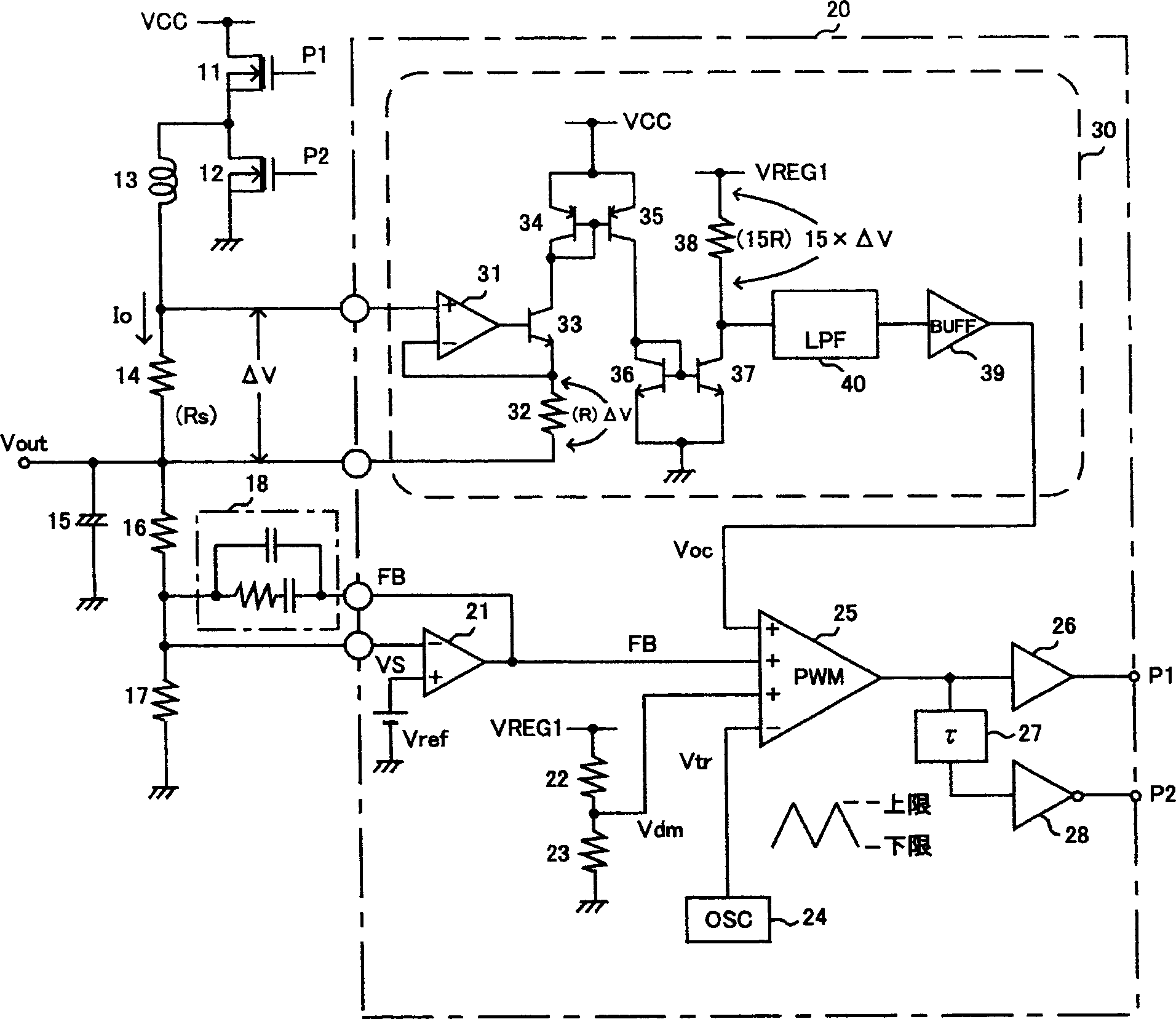
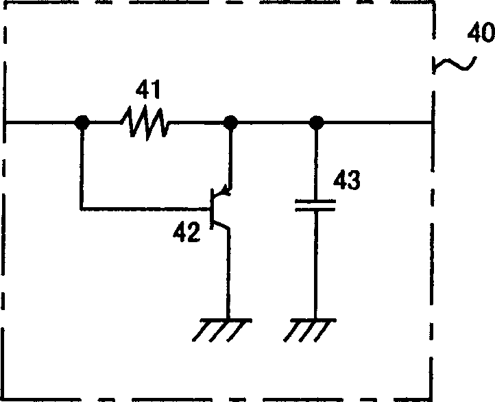
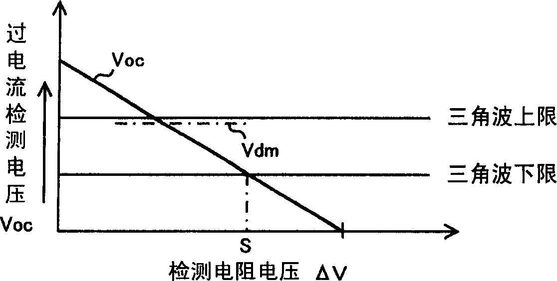
[0025] figure 1 is a configuration diagram showing a switching power supply device according to an embodiment of the present invention, figure 2 expressed in figure 1 The composition of the low-pass filter used in . in addition, image 3 is to illustrate the use of figure 1 A diagram of the current limiting effect of a switching power supply device, Figure 4 It is a graph showing the output voltage-output current characteristic.

[0026] exist figure 1 Among them, between the power supply voltage VCC and the ground, a high-side switch 11 (hereinafter referred to as the first switch) composed of an N-type MOS transistor (hereinafter referred to as NMOS) and a low-side switch 12 composed of NMOS transistors (hereinafter referred to as the second switch) are connected in parallel. ). The output voltage is output through a ...


PUM


Abstract

In a switching power source apparatus which outputs a DC output voltage converted from a DC power source voltage, the DC output voltage is compared with a reference voltage to generate a feedback signal which decreases as the DC output voltage increases. A current detecting signal which decreases as the output current increases is also generated. The smaller one of the feedback signal and the current detecting signal as a comparison signal is compared with a triangular signal in a PWM comparator to produce a PWM signal. A semiconductor switch is on-off controlled by the PWM signal. Therefore, the apparatus can perform a constant voltage control with a current limit function, which can improve the accuracy of a current limit operation, eliminate the need of a special high speed operation of a current detecting circuit and a driver and stabilize the output voltage during the operation of current limit.

Description

technical field [0001] The invention relates to a switching power supply device for DC-DC conversion with constant voltage control with current limiting function. Background technique [0002] Conventionally, in switching power supply devices that perform constant voltage control with a current limiting function, the current is limited by a pulse-by-pulse method. [0003] Figure 5 It is a diagram showing the configuration of a conventional switching power supply device that uses constant voltage control that limits current by a pulse-by-pulse method. [0004] exist Figure 5 Among them, between the power supply voltage VCC and the ground, a current detection resistor 51, an N-type MOS transistor (hereinafter referred to as NMOS) as a high-side switch 52 and an NMOS as a low-side switch 53 are connected in parallel. The output voltage is output through a smoothing coil 54 and a smoothing capacitor 55 connected from the connection point of the high-side switch 52 and the low...

Claims


Application Information

Patent Timeline
Patent Type & Authority Applications(China)
IPC IPC(8): H02M3/155H02M3/158
CPCY02B70/1466H02M3/1588H02M2001/0009H02M1/0009Y02B70/10
Inventor 安藤弘明星野太一
Owner ROHM CO LTD
Why Eureka
Try Eureka