Control box assembly for air conditioner

An air conditioner and control box technology, which is used in heating and ventilation control systems, space heating and ventilation, and household heating, etc., can solve problems such as unreasonable structure of control box components, and achieve the effect of convenient assembly and small volume.

Inactive Publication Date: 2004-06-09
LG ELECTRONICS (TIANJIN) APPLIANCES CO LTD
View PDF0 Cites 2 Cited by
  • Summary
  • Abstract
  • Description
  • Claims
  • Application Information

AI Technical Summary

Problems solved by technology

[0014] In order to overcome the problem of the unreasonable structure of the control box assembly in the existing air conditioner, the present invention provides a control box assembl

Method used


Image

  • Control box assembly for air conditioner
  • Control box assembly for air conditioner
  • Control box assembly for air conditioner

Examples


Embodiment Construction

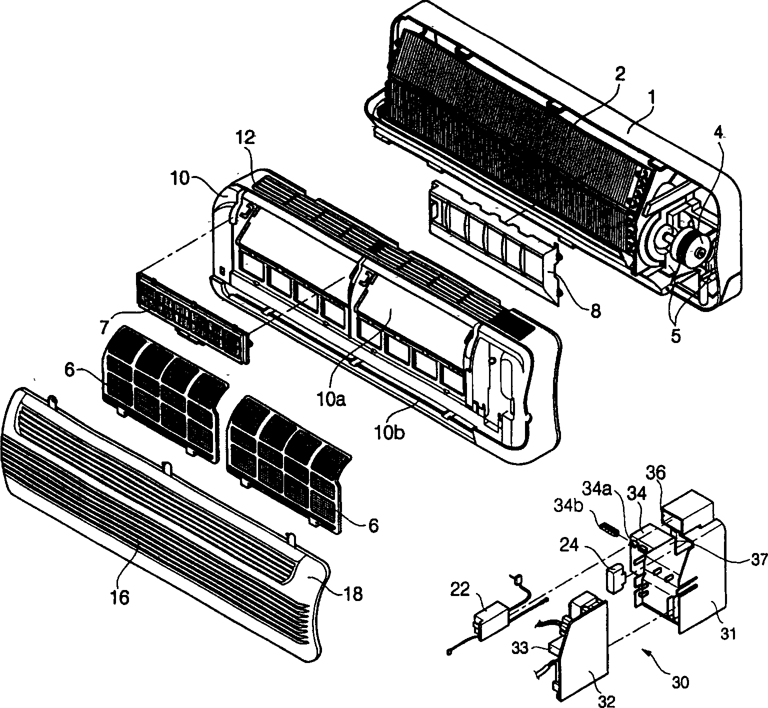
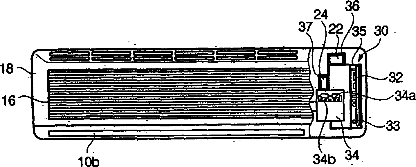
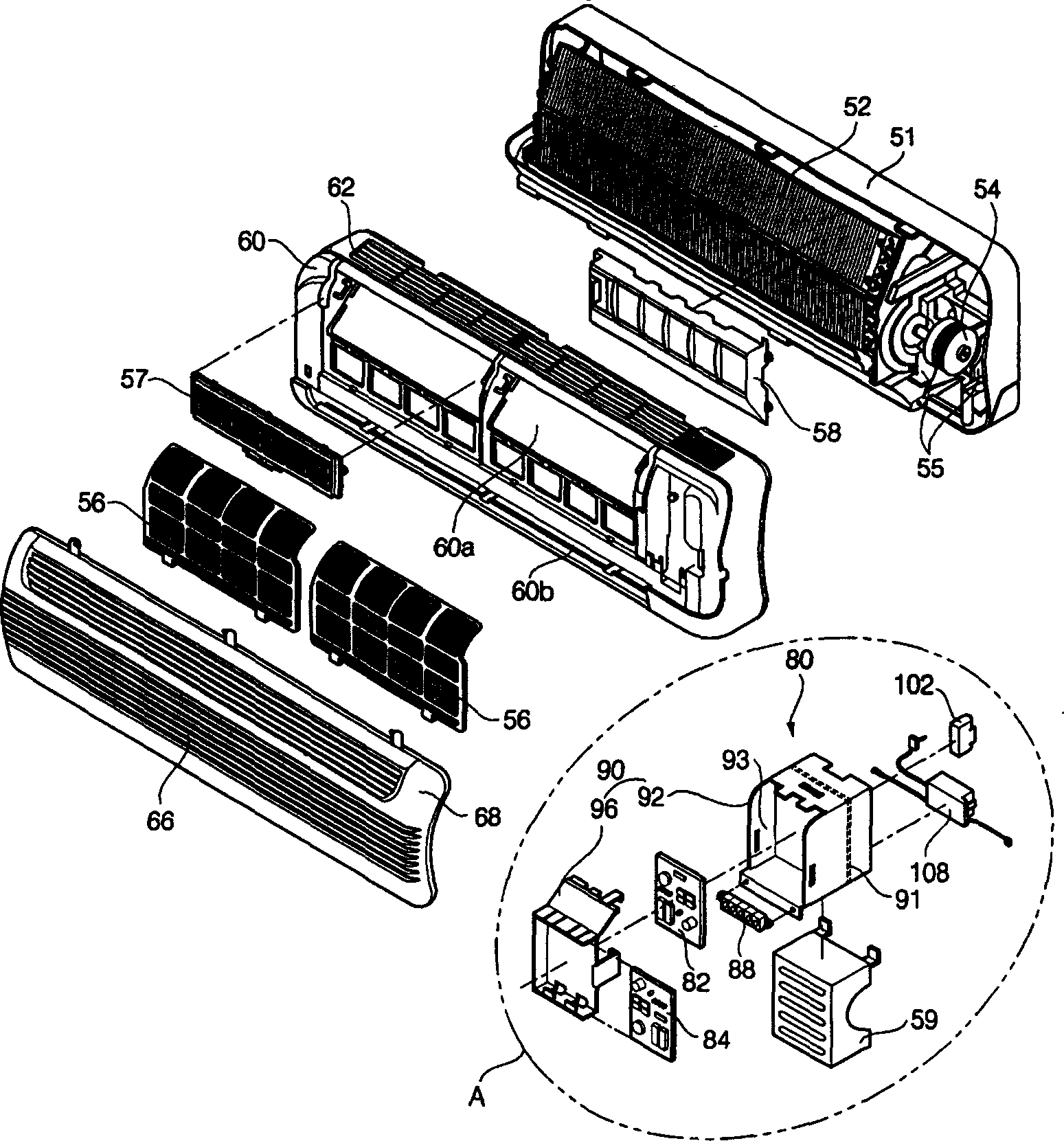
[0040] Such as Figure 3 to Figure 5 As shown, the air conditioner of the present invention comprises a shell (sheath) (51), assembled in the front of the shell (51) so as to form a space for accommodating the heat exchanger (52) and the motor (54) together with the shell (51) , and formed a grid part (grill) (62) along the horizontal direction above, the front panel (60) of the air inlet (60a) and air outlet (60b) was formed in the front, and the front panel (60) was installed on the front panel (60) with a hinge And can rotate, and form the inlet grille (68) of grille part (66) along the transverse direction.

[0041]Between the shell (51) and the heat exchanger (52), a shaft (not shown) connected to the motor (54) is installed, which can rotate with the motor when the motor (54) is driven to generate a transmission. Wind blowing fan (not shown), between the heat exchanger (52) and the air intake grille (68), an air filter (56) capable of filtering foreign matter mixed in t...


PUM


Abstract

The present invention relates to a control box component of air conditioner. It includes control box casing, printed circuit base boards on which the electronic elements are mounted in the casing and mounting plate for mounting electronic device. In the invented control box component AC electric elements and DC electronic elements are respectively mounted on the different printed circuit base boards, and respectively mounted on the different positions. The capacitor and high-voltage generator are respectively mounted on the panels of different two sides in the rear portion of the control box.

Description

technical field [0001] The present invention relates to an air conditioner, and more particularly to a control box for its electronic components. Background technique [0002] Generally speaking, air conditioners are installed to provide people with a comfortable indoor environment by heating, cooling or purifying indoor air through heaters, air conditioners, air conditioners, etc. [0003] figure 1 The disassembled side of the structure of the main part which is an example of the prior art air conditioner is a diagram, figure 2 for figure 1 An enlarged side view of part A of the image 3 An example of a prior art air conditioner has a partially cutaway front view. [0004] Such as Figure 1 to Figure 3 As shown, the existing air conditioner includes a shell (sheath) (1), assembled in front of the shell (1) so as to form a space for accommodating the heat exchanger (2) and the motor (4) together with the shell (1) , and the grille (grill) (12) is formed in the horizon...

Claims


Application Information

Patent Timeline
IPC IPC(8): F24F11/00
Inventor 朴泰秉金玄镐
Owner LG ELECTRONICS (TIANJIN) APPLIANCES CO LTD
Why Eureka
Try Eureka