Automatic skimming method and apparatus

A slag removal and automatic technology, applied in mechanical cleaning, manufacturing tools, metal processing equipment, etc., can solve the problems of high labor intensity for operators

Inactive Publication Date: 2004-06-30
BAOSHAN IRON & STEEL CO LTD
View PDF0 Cites 16 Cited by
  • Summary
  • Abstract
  • Description
  • Claims
  • Application Information

AI Technical Summary

Problems solved by technology

[0003] The present invention overcomes the defects that the existing slag removal device adopts manual operation, the labor intensity of operators is high, and the slag removal effect is random, and provides an automatic slag removal

Method used


Image

  • Automatic skimming method and apparatus
  • Automatic skimming method and apparatus
  • Automatic skimming method and apparatus

Examples


Embodiment Construction

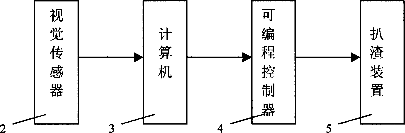
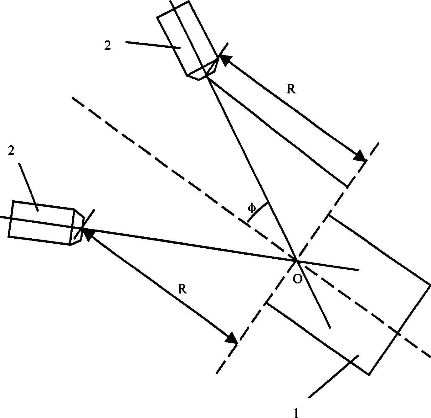
[0015] see figure 2 , image 3 , Figure 4 , an automatic slag removal method, which is to detect steel slag on the surface of ladle 1 by visual sensor 2, input the detected image into computer 3, and output signal to programmable controller 4 to control manipulator 5 of slag removal device after computer 3 processes the image. Slagging operation. The method of computer image processing and output control manipulator is:

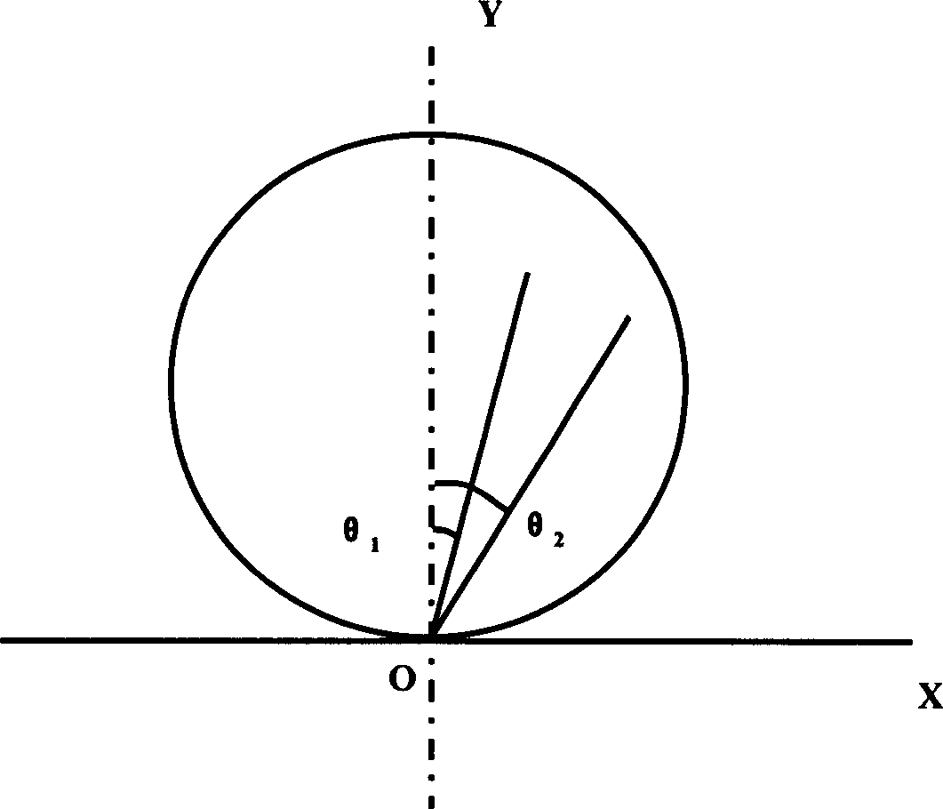
[0016] (1) First identify the target steel slag position, determine the steel slag position by pre-setting the surface partition, set the starting point as zero, the rotation angle as θ, the rotation angle and the surface Y axis form angles θ1, θ2,… θn, divide the surface into several fan-shaped areas, set the value of θ (-90°<θ<90°), then θ1=θ, θ2=2θ, θ3=3θ, θ4=4θ...θn=nθ, divide the entire surface area is n areas;

[0017] (2) Locate the target slag, and judge that the steel slag is at a certain position through the visual sensor;

[0018] (3) Judgi...


PUM


Abstract

The present invention relates to a skimming method for auxiliary equipment in steel-smelting technique and an automatic skimming machine. It is characterized by that a visual sensor is mounted over the ladle, said visual sensor can be used for detecting steel slag on the surface of ladle, then the detected image can be inputted into computer, after having been processed by computer a signal can be outputted by computer and transferred into programmable controlled to control manipulator of skimming machine to implement skimming operation.

Description

technical field [0001] The invention relates to a slag removal method and a slag removal device for auxiliary equipment in steelmaking technology. technical background [0002] In steelmaking production, it is necessary to remove steel slag before casting to avoid resulfurization and rephosphorization of molten steel, so as to make molten steel more pure and obtain high-quality billets. The existing ladle (or ladle) slag removal process is relatively simple, relying only on manual visual inspection of the steel slag level and manual operation of the slag removal machine to carry out slag removal. The slag removal effect is random, which affects the casting quality. The labor intensity of the operator is relatively high. Contents of the invention [0003] The present invention overcomes the defects that the existing slag removal device adopts manual operation, the labor intensity of operators is high, and the slag removal effect is random, and provides an automatic slag re...

Claims


Application Information

Patent Timeline
IPC IPC(8): B22D43/00
Inventor 陆丽华
Owner BAOSHAN IRON & STEEL CO LTD
Why Eureka
Try Eureka