
Liquid crystal displaying devices

A technology of liquid crystal display devices and thin film transistors, which is applied in identification devices, nonlinear optics, instruments, etc., and can solve problems such as color saturation differences in reflection areas and penetration areas

Inactive Publication Date: 2004-07-07
TPO DISPLAY
View PDF0 Cites 4 Cited by
  • Summary
  • Abstract
  • Description
  • Claims
  • Application Information

AI Technical Summary

Problems solved by technology

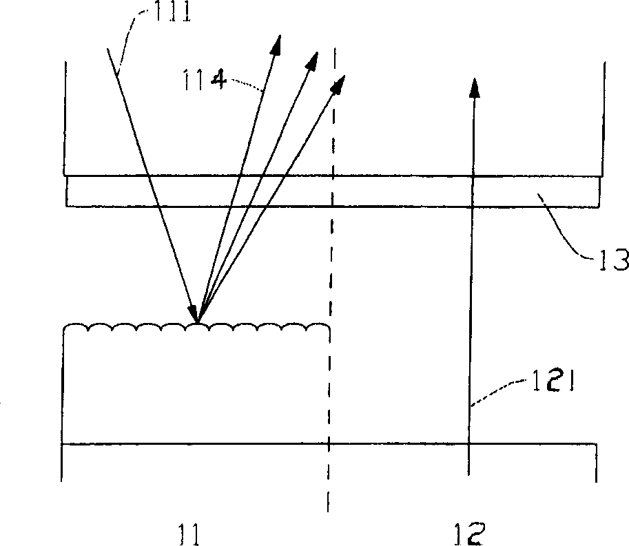
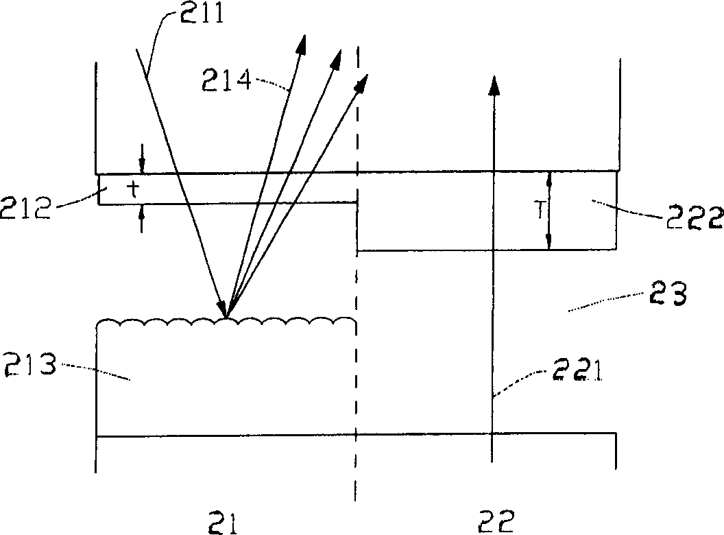
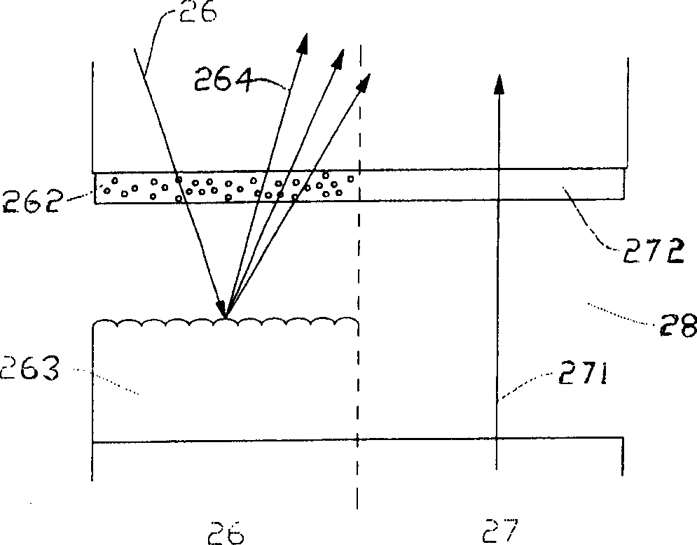
[0008] An object of the present invention is to provide a liquid crystal display device, through the color filters of two transparent substrates, to solve the problem of color saturation difference between the reflection area and the transmission area

Method used


Image

  • Liquid crystal displaying devices
  • Liquid crystal displaying devices
  • Liquid crystal displaying devices

Examples


Embodiment Construction

[0040] Some embodiments of the present invention are described in detail as follows. However, the present invention can be widely implemented in other embodiments other than those described in detail, and the scope of the present invention is not limited, which is subject to the scope of the following patents.

[0041] For details of the first embodiment of the present invention, see image 3 Single pixel top view and Figure 4 A cutaway view of a sub-pixel. The single pixel 30 of the color liquid crystal display will include three sub-pixels 31, 32, 33, and the colors of each sub-pixel are three primary colors of red, green and blue respectively. That is, if the sub-pixel 31 is a red sub-pixel, then the sub-pixel 32 is a green sub-pixel, and the sub-pixel 33 is a blue sub-pixel. In a transflective liquid crystal display, each sub-pixel can be divided into two parts: transmissive areas 312 , 322 , 332 and reflective areas 311 , 321 , 331 .

[0042] Figure 4 What is shown i...


PUM

PropertyMeasurementUnit
thicknessaaaaaaaaaa

Abstract

A liquid crystal display unit can realize optimization of contrast ratio and degree of saturation for penetration region and reflection region on colour liquid crystal display by adjusting thickness of colour filter for two transparent base plates at top and bottom. It comprises the first base plate with multifilm transistor for limiting reflection and penetration region, an insulation layer on the first base plate, the first colour filter on the insulation layer, a padded high insulation layer on part of the first colour filter, the first electrode covering the padded high insulation layer and part of the first colour filter, a liquid crystal layer on the first electrode, the second colour filter, the secone electrode and the second base plate.

Description

technical field [0001] The invention relates to a liquid crystal display device, in particular to a semi-transmissive and semi-reflective liquid crystal display device. By adjusting the thickness of the color filter (color filter) of the upper and lower transparent substrates, the color liquid crystal display can be achieved. Optimized contrast ratio and color saturation in transmissive and reflective areas. Background technique [0002] The color liquid crystal display panel includes two transparent substrates and a liquid crystal layer placed between the transparent substrates. Generally speaking, in a thin film transistor (TFT: Thin Film Transistor) panel, a color filter is only formed on a transparent substrate facing the thin film transistor, that is, the color filter and the thin film transistor are located on different sides. on the transparent substrate and face each other. [0003] In a full-transmissive or full-reflective color liquid crystal display, since the l...

Claims


Application Information

Patent Timeline
Patent Type & Authority Applications(China)
IPC IPC(8): G02F1/1333G02F1/1335G09F9/35
Inventor 张世昌蔡耀铭
Owner TPO DISPLAY
Learn More