Tunable dual band antenna system

A dual-band antenna, antenna technology, applied in antennas, transmission systems, resonant antennas, etc., can solve problems such as increasing system cost and complexity, increasing the size and complexity of wireless phones, etc.

Inactive Publication Date: 2004-07-07
SIERRA WIRELESS
View PDF0 Cites 17 Cited by
  • Summary
  • Abstract
  • Description
  • Claims
  • Application Information

AI Technical Summary

Problems solved by technology

However, dual antennas and frequency switching increase the size and complexity of the wireless phone
Two antennas take up twice the space of one antenna, and frequen

Method used


Image

  • Tunable dual band antenna system
  • Tunable dual band antenna system
  • Tunable dual band antenna system

Examples


Embodiment Construction

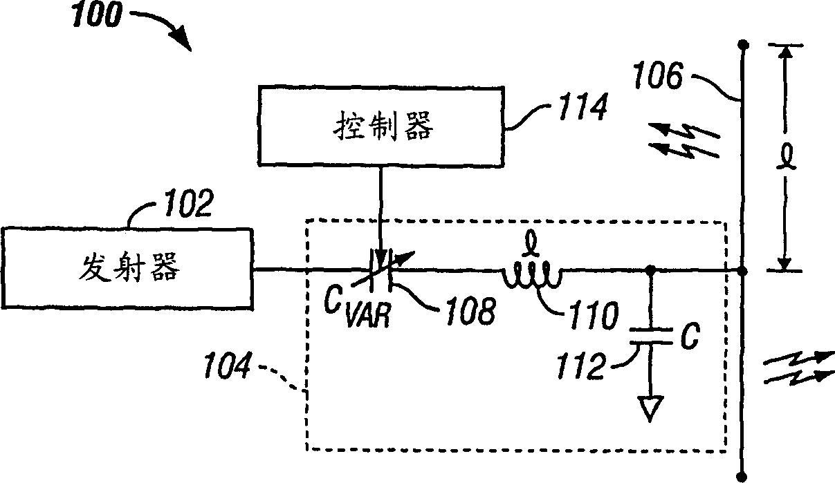
[0020] Reference is now made to the drawings, wherein the drawings are for purposes of illustration only and are not limiting of the preferred embodiments of the invention. image 3 is a circuit block diagram of the dual-band antenna system 100 . The antenna system 100 includes a transceiver 102 electrically connected to a matching network 104 . It is obvious to those skilled in the art that the transceiver 100 can also be a receiver or a transmitter according to specific applications. Such as image 3 As shown, the matching network 104 is connected to a dipole antenna 106 of length l. The length l is typically 1 / 4 of the length of the lower band wavelength. The matching network 104 is used to implement impedance matching between the antenna 106 and the transceiver 102 with two specified frequency bandwidths.

[0021] Specifically, refer to image 3 , the matching network 104 has a variable capacitor 108 , the first wire of which is electrically connected to the transceiver ...


PUM


Abstract

A tunable dual band antenna system is disclosed. The system includes a transceiver, a matching network and an antenna. The matching network is operable to tune the antenna to the transceiver at both a first and second frequency. Accordingly, the matching network has a variable capacitor, an inductor and a second capacitor. The value of the variable capacitor is chosen to tune the antenna at the first frequency and the second frequency such that the system can be used to transmit and receive electromagnetic energy over two bandwidths. The values of the variable capacitor, the inductor, and the second capacitor are chosen to minimize the standing wave ratio of the system at both the first frequency and the second frequency.

Description

technical field [0001] The present invention generally relates to an antenna matching network, and more particularly to a matching network for a tunable dual-band antenna. Background technique [0002] To ensure maximum energy transfer from a radio frequency (RF) transmitter to the antenna, the impedance between the antenna and the transmitter used for frequency transmission should be matched. Antennas will transmit signals most efficiently if the impedances are matched. However, if the impedances are not matched, the transmitted energy will be lost and the performance of the antenna will degrade. [0003] In order to match the impedance between the transmitter and the antenna, a matching network needs to be set up. For a normal dipole antenna, the matching network matches the impedance of the dipole antenna to that of the transmitter. Referring to Figure 1, a prior art matching network 10 for a transmitter 12 and a dipole antenna 14 is shown. The transmitter 10 generate...

Claims


Application Information

Patent Timeline
IPC IPC(8): H01Q5/00H01Q5/335H01Q21/30H04B1/04
CPCH04B1/0458H04B1/005H01Q9/14H01Q21/30H01Q5/0041H03H7/40H01Q5/335H01Q5/00
Inventor 安德雷·格莱尔
Owner SIERRA WIRELESS
Why Eureka
Try Eureka