Supercharge Your Innovation With Domain-Expert AI Agents!

Oil separator device of piston ring air channeling

A technology of piston rings and oil separators, applied in the direction of machine/engine, engine lubrication, engine components, etc., can solve problems such as air pollution, exhaust deterioration, and reduction of lubricating oil volume

Inactive Publication Date: 2004-07-14
MAHLE FILTER SYST JAPAN CORP
View PDF0 Cites 7 Cited by
  • Summary
  • Abstract
  • Description
  • Claims
  • Application Information

AI Technical Summary

Problems solved by technology

Causes exhaust to deteriorate and reduces the amount of lubricating oil that acts as a lubricant, leading to air pollution and engine scuffing

Method used


Image

  • Oil separator device of piston ring air channeling
  • Oil separator device of piston ring air channeling
  • Oil separator device of piston ring air channeling

Examples


Embodiment Construction

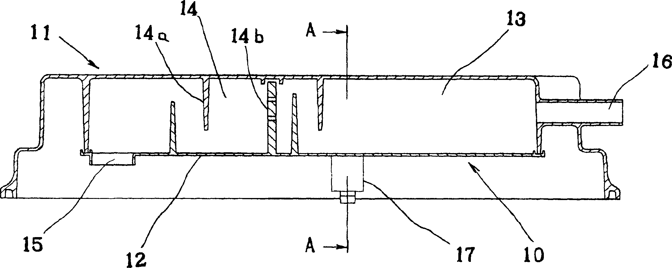
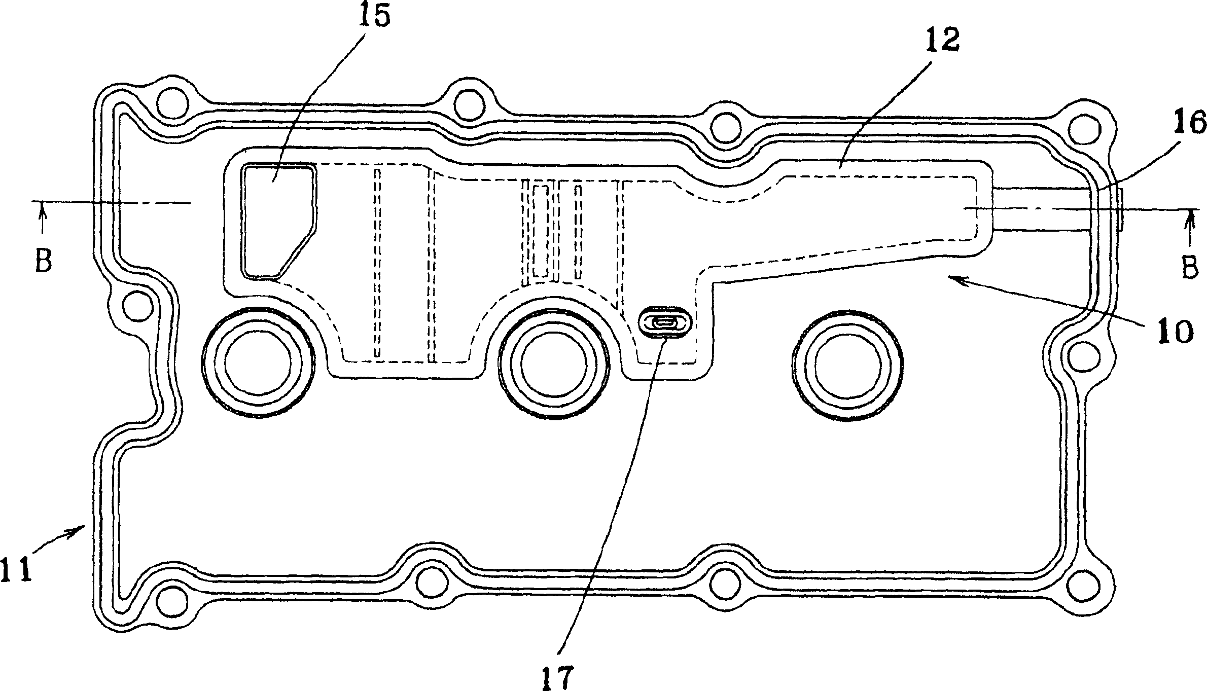
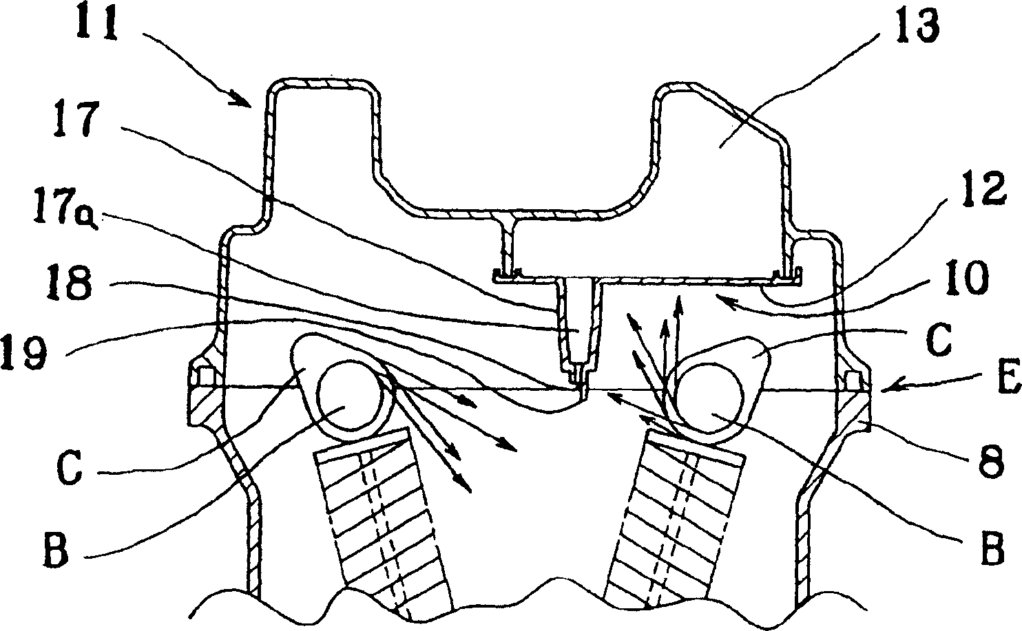
[0017] figure 1 In Fig. 4, the oil separator device 10 of the present invention is formed in a box-shaped cylinder head cover 11 which is formed of polyamide resin containing glass fibers and has an open bottom, and is fixedly installed from the inside of the cylinder head cover. The upper wall begins to divide the inner bottom cover body 12 at intervals, and a lubricating oil separation chamber 13 is formed between the bottom cover body 12 and the upper wall of the cylinder head cover 11 . Inside the lubricating oil separation chamber 13, a lubricating oil separating device 14 is arranged in a labyrinthine manner with a partition plate 14a and a perforated plate 14b, and a piston ring blow-by gas inlet 15 is set on one side of the bottom cover body 12, and on the other side One side is provided with a tubular outlet 16 penetrating the side wall of the cylinder head cover 11, and on the bottom cover 12, an oil discharge pipe 17 is hung down, and the oil discharge pipe 17 is a...


PUM


Abstract

A bottom lid body 12 for dividing the inside at an interval from the upper wall of a cylinder head cover 11 is fixed. An oil separation chamber 13 is formed between the bottom lid body 12 and the cylinder head cover 11. A collar piece 19 for cutting off scattered oil from the lower portion generated by centrifugal force in a camshaft B, a cam C, and the like is provided at one side of a drain hole 18 provided at the lower end of a drain pipe 17 that is perpendicularly provided from the bottom lid body 12.

Description

technical field [0001] The present invention relates to an oil separator device for separating lubricating oil contained in piston ring blow-by gas leaking from the inside of an engine. technical background [0002] In the engine for vehicles, in order to prevent air pollution, when the piston ring blow-by gas leaked from the engine is returned to the intake pipe again, the mist lubricating oil contained in the piston ring blow-by gas is separated and returned to the suction pipe. Oil separator device on the sliding part side of the engine. [0003] Figure 8 Among them, the existing oil separator device is formed by aluminum die-casting or polyamide, polyacetal and other synthetic resins, and the bottom is open, inside the box-shaped cylinder head cover 1, and the The upper wall partitions the inner bottom cover body 2 at intervals, and a lubricating oil separation chamber 3 is formed between the bottom cover body 2 and the upper wall of the cylinder head cover 1 . Inside...

Claims


Application Information

Patent Timeline
IPC IPC(8): F01M13/04F01M11/08F01M13/00
Inventor 山崎敦司
Owner MAHLE FILTER SYST JAPAN CORP
Features
  • R&D
  • Intellectual Property
  • Life Sciences
  • Materials
  • Tech Scout
  • Unparalleled Data Quality
  • Higher Quality Content
  • 60% Fewer Hallucinations
Learn More