High-low pressure dome type compressor
A technology for high and low pressure compressors, applied in the field of high and low pressure dome compressors, which can solve the problems of reducing shaft rigidity, increasing the number of sealing related parts, increasing the number of drive shaft processing, etc., and achieving the effect of improving separation efficiency
- Summary
- Abstract
- Description
- Claims
- Application Information
AI Technical Summary
Problems solved by technology
Method used
Image
Examples
Embodiment approach 1
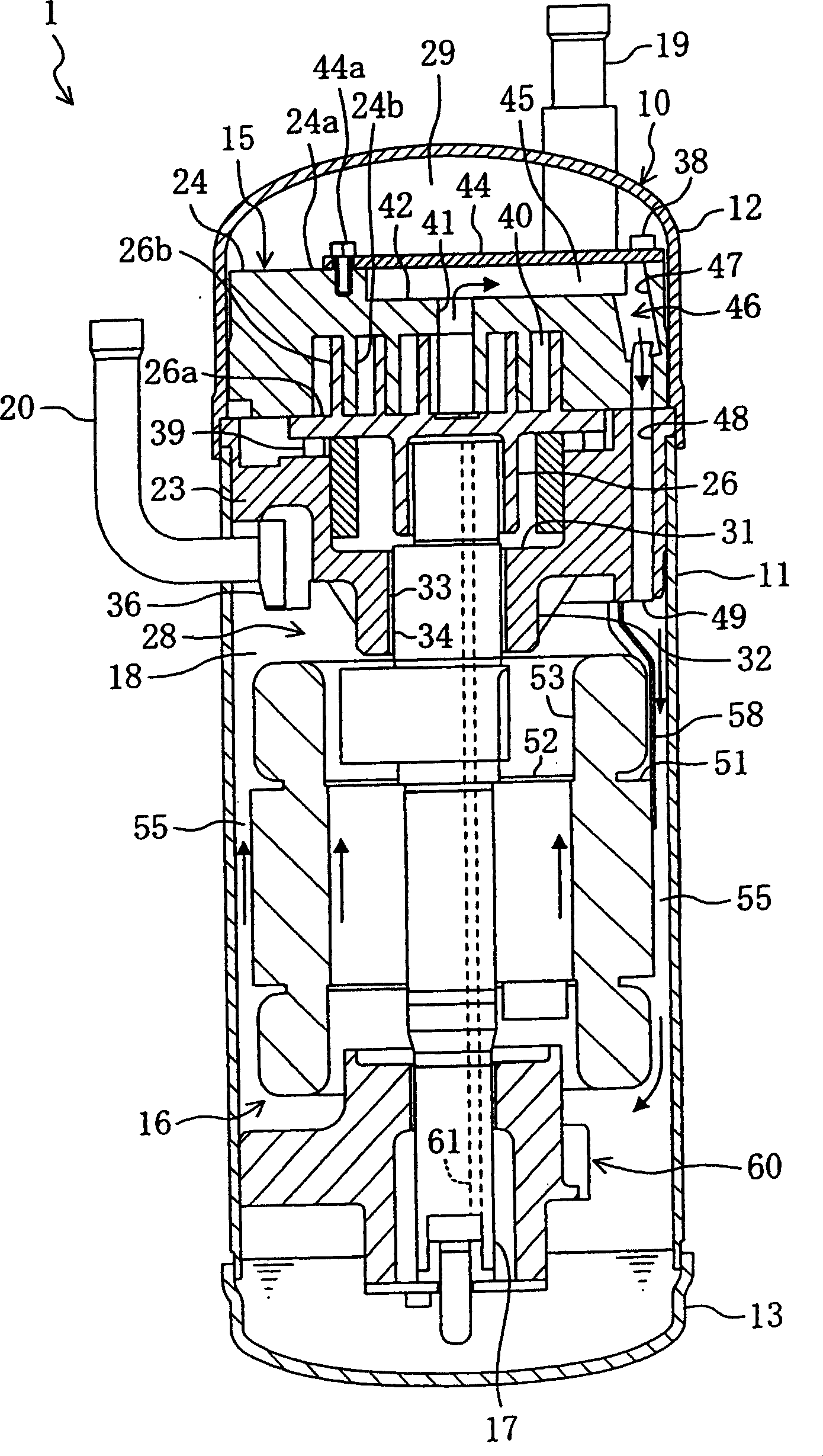
[0073] like figure 1 As shown, the high-low pressure dome compressor 1 of this embodiment is connected to a refrigerant circuit that circulates refrigerant gas to perform a refrigeration cycle, although not shown, and compresses refrigerant gas as a working fluid.
[0074] The compressor 1 is provided with a vertically long cylindrical sealed dome-shaped casing 10 . The casing 10 is composed of the following components to form a pressure vessel: a casing body 11, which is a cylindrical body portion with an axis extending in the up-down direction; a bowl-shaped upper wall portion 12, which is welded to its upper end in an airtight manner and joined together. , and has a convex surface protruding above; the bowl-shaped bottom wall portion 13 is hermetically welded at its lower end and joined together, and has a convex surface protruding below; and the inside of the shell 10 is hollow.
[0075] Inside the casing 10 are housed a compression mechanism 15 for compressing refrigeran...
Embodiment approach 2
[0124] Regarding the guide plate 58 provided in the high-low pressure dome-type compressor 1 of the second embodiment, as shown in FIG. 10 , the distribution concave portion 90 is omitted. In addition, here, the same code|symbol is attached|subjected to the same component as Embodiment 1, and the description is abbreviate|omitted.
[0125] Specifically, the guide plate 58 includes a guide body 84 and wing portions 85 arranged at both ends of the guide body 84 . The guide body 84 is provided with a lower curved plate 86 whose cross section is arc-shaped and extends linearly up and down; Formed to protrude toward the inner edge side; and side wall portions 88 are formed upright toward the outer edge side on both end sides of the lower curved plate 86 and the protrusion portion 87 .
[0126] The above-mentioned wing portion 85 is an end portion joined to the outer edge side of the side wall portion 88 of the guide body 84 , and is formed to have an arcuate cross-section and exte...
Embodiment approach
[0132] In each of the above-mentioned embodiments, the compression mechanism 15 is not limited to a scroll type, and may be configured, for example, as a rotary piston type.
[0133] In addition, each of the above-mentioned embodiments may have a configuration in which the noise reduction space 45 of the compression mechanism 15 is omitted.
[0134] In addition, in Embodiment 1 described above, a configuration in which the guide plate 58 is omitted may also be employed. In addition, in Embodiment 1 described above, the driving motor 16 is not limited to being constituted by a DC motor, and may be constituted by, for example, an AC motor.
[0135] In addition, in the above-mentioned second embodiment, the configuration is not limited to the configuration in which the inner end portion 36 of the discharge pipe 20 protrudes further inside than the inner surface of the casing main body 11 .
[0136] In addition, in each of the above-mentioned embodiments, the cross section of the...
PUM
 Abstract
Description
Claims
Application Information
 - R&D
- Intellectual Property
- Life Sciences
- Materials
- Tech Scout
- Unparalleled Data Quality
- Higher Quality Content
- 60% Fewer Hallucinations
Browse by: Latest US Patents, China's latest patents, Technical Efficacy Thesaurus, Application Domain, Technology Topic, Popular Technical Reports.
© 2025 PatSnap. All rights reserved.Legal|Privacy policy|Modern Slavery Act Transparency Statement|Sitemap|About US| Contact US: help@patsnap.com


