Device for stabilovolt power source and switching power source device and electronic instrument using such device

A technology of regulated power supply and switching power supply, applied in other fields, can solve the problems such as the large influence of resistance r11 and the time spent on safety specification testing.

Inactive Publication Date: 2004-08-11
SHARP KK
View PDF1 Cites 3 Cited by
  • Summary
  • Abstract
  • Description
  • Claims
  • Application Information

AI Technical Summary

Problems solved by technology

[0013] In the IC11 of the above-mentioned prior art, the influence of variation of the overcurrent detection resistor r11 constituted by the aluminum wiring pattern is large, and in the overload test for the safety standard of the power supply of the product, the Figure 11 , as indicated by reference numerals α1 to α2, for exa

Method used


Image

  • Device for stabilovolt power source and switching power source device and electronic instrument using such device
  • Device for stabilovolt power source and switching power source device and electronic instrument using such device
  • Device for stabilovolt power source and switching power source device and electronic instrument using such device

Examples


no. 1 approach

[0039] Regarding the first embodiment of the present invention, the following is based on figure 1 , figure 2 and the above Figure 11 Be explained.

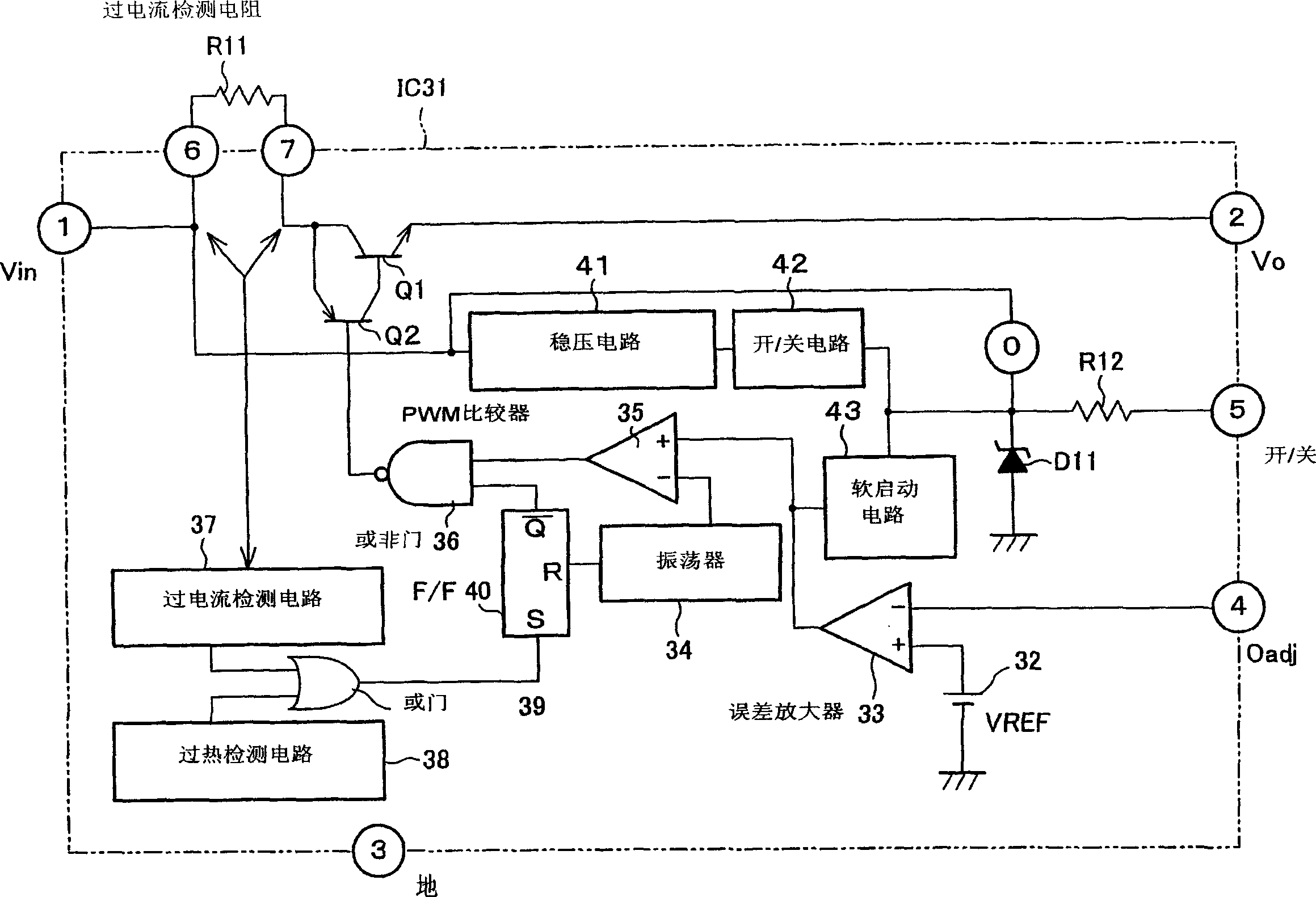
[0040] figure 1 It is a block diagram showing the electrical structure of IC31 of 1st Embodiment of this invention. Use the IC31 as the above Figure 9 IC2 in the switching power supply device 1 shown in the figure 1 in, with the above Figure 9 Corresponding parts are denoted by the same reference numerals. The structure of this IC31 includes each power transistor Q1 and Q2, a reference voltage source 32, an error amplifier 33, an oscillator 34, a PWM comparator 35, a NOR gate 36, a resistor R11 for detecting an overcurrent, an overcurrent detection circuit 37, Overheat detection circuit 38, OR gate 39, trigger 40, voltage stabilizing circuit 41, switch circuit 42, soft start circuit 43, voltage stabilizing diode D11 and resistor R12.

[0041] The error amplifier 33 amplifies the difference between the feedback voltag...

no. 2 approach

[0053] The following is based on image 3 A second embodiment of the present invention will be described.

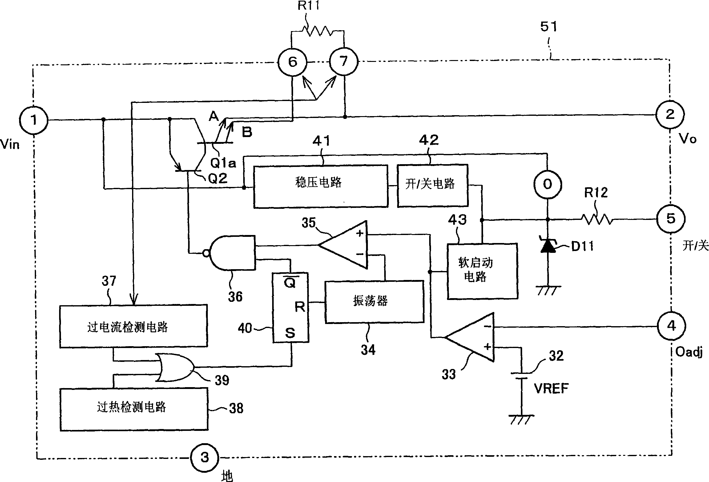
[0054] image 3 It is a block diagram showing the electrical structure of IC51 of 2nd Embodiment of this invention. This IC51 is similar to the above-mentioned IC31, and the same parts are denoted by the same reference numerals, and description thereof will be omitted.

[0055] Note that in this IC51, the P-type power transistors inserted in series on the power supply line are multipolar emitter outputs as indicated by reference numeral Q1a. Therefore, the above-mentioned overcurrent detection resistor R11 is provided on the emitter side of the power transistor Q1a, and the terminal on the large current side indicated by the reference symbol A with respect to the above-mentioned power transistor Q1a is connected to the second output terminal as usual. The terminal on the side of the small current (for example, 1 / 1000 of the above-mentioned high-current side terminal A...

no. 3 approach

[0058] based on the following Figure 4 A third embodiment of the present invention will be described.

[0059] Figure 4 It is a block diagram showing the electrical structure of IC61 of 3rd Embodiment of this invention. This IC61 is similar to the above-mentioned IC51, and the same parts are denoted by the same reference numerals, and description thereof will be omitted. Note that in this IC61, instead of the power transistors Q1 and Q2 described above, a power MOSFET with a current readout function is used as indicated by reference numeral Q12. Therefore, one end of the overcurrent detection resistor R11 is connected to the readout terminal of the power MOSFET indicated by reference sign B via the sixth terminal, and the seventh terminal connected to the other end of the overcurrent detection resistor R11 , and connect to the 2nd terminal of the output. The low ** switching pulse from the NOR gate 36 is supplied to the gate of the P-type power MOSFET 12 .

[0060] Ther...


PUM


Abstract

A stabilized power supply-use device of the present invention, which is mounted on a switching power supply, is an IC into which power transistors, a control circuit for controlling a base current of the power transistors, and other electronic components are formed, and an overcurrent detecting resistor connected in series with the power transistor is realized by a resister provided externally to the IC. Therefore, as compared to the overcurrent detecting resistor being made up of aluminum wiring patterns inside the IC, the overcurrent detecting resistor of the present invention dramatically decreases variations in value of resistance, whereby it is possible to improve an accuracy of voltage detection and to arbitrarily set a value of resistance. This eliminates the need for a needlessly increased input power capacity in a test based on safety standard and other tests, thereby enabling a switching power supply manufactured at a lower cost.

Description

field of invention [0001] The present invention relates to a device for a stabilized power supply, such as a power supply device for video, etc., by using the on-resistance of the power transistor to reduce the input voltage while switching, the input voltage is stabilized to a desired voltage and output, and its control circuit etc. and the above-mentioned power transistor are integrated into an integrated circuit to constitute the main part of the stabilized power supply device. In addition, the present invention also relates to a switching power supply device and an electronic instrument using the stabilized power supply device. Background of the invention [0002] Figure 9 It is a block diagram showing the electrical configuration of a general switching power supply device 1 used in the above-mentioned video power supply device and the like. This switching power supply device 1 has an input terminal P1, an output terminal P2, and a ground terminal P3. It is a so-called ...

Claims


Application Information

Patent Timeline
IPC IPC(8): H02M3/155G05F1/573H03K17/08H03K17/60H03K17/687
CPCG05F1/573H01L2224/32245H01L2224/48247H01L2224/48257H01L2224/73265H01L2924/13091H01L2924/00
Inventor 因幡克己
Owner SHARP KK
Why Eureka
Try Eureka