PET scanner

A technology of positron emission and scanner, which is applied in the direction of instruments, circuits, electrical components, etc., and can solve problems such as the difficulty of determining the collision layer

Inactive Publication Date: 2004-08-11
EUROPEAN ORGANIZATION FOR NUCLEAR RESEARCH
View PDF4 Cites 10 Cited by
  • Summary
  • Abstract
  • Description
  • Claims
  • Application Information

AI Technical Summary

Problems solved by technology

When using LSO and GSO detectors, pulse shape discrimination is used to determine the collision layer, however, the disadvantage of this particular setup is that the decay time constants of the fast and slow LSO differ by only 10% (4-5 ns at an average of 40 ns)

Method used


Image

  • PET scanner
  • PET scanner
  • PET scanner

Examples


Embodiment Construction

[0035] PET embodying the present invention uses a scintillator comprising lutetium-based crystals. Specifically, the scintillator embodying the present invention uses LuAP or LuYAP, and hereinafter, the acronym LuAP may represent LuAP or LuYAP. This material has many properties that make it useful as a scintillator.

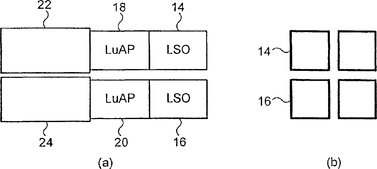
[0036] Figures 2(a) and (b) show two scintillators for PET scanners, each comprising an inner layer of LSO14,16 and a layer of LuAP18,20. The thickness of each LSO and LuAP layer is preferably less than 20mm. Adjacent to and optically coupled to each LuAP layer 18,20 is a photodetector 22,24 for detecting light emitted from either the LSO 14,16 or the LuAP 18,20. The photodetectors 22, 24 may be of any suitable type, but typically include photomultipliers or avalanche photodiodes. The signals from the photodetectors 22, 24 are processed (not shown) by electronic readouts. In fact, according to the conventional layout of PET scanners, a plurality of scintillat...


PUM


Abstract

A positron emission camera comprising a plurality of scintillators, wherein the scintillators comprise LuAlO3:Ce (LuAP) based crystals (18,20). In particular, the scintillation crystals (18,20) are LuAP and/or LuYAP.

Description

technical field [0001] The present invention relates to a positron emission tomography (PET) camera or scanner. Background technique [0002] PET scanners are well known in the field of medical physics. These scanners create images of the body by detecting radiation emitted from radioactive materials injected into the body. Each scanner consists of radiation detectors (commonly called scintillators) arranged in a ring configuration around a movable patient platform. FIG. 1 shows a typical configuration with a detector ring 10 and a patient platform 12 . Each scintillator includes a crystal and an associated crystal located opposite it on the ring. Many known cameras use Bi 4 Ge 3 o 12 (BGO) as a scintillation detector as taught in US Patent 4,843,245 and EP 0,437,051B. Each scintillator is connected to a photomultiplier tube, which in turn is connected to an electronic readout. [0003] During the scanning process, the patient is placed on a movable table in the cent...

Claims


Application Information

Patent Timeline
IPC IPC(8): G01T1/161C09K11/00C09K11/79C09K11/80G01N1/00G01T1/20G01T1/202G01T1/29H01L31/09
CPCG01T1/2985G01T1/202A61B6/037G01T1/2008G01T1/164
Inventor L·保罗
Owner EUROPEAN ORGANIZATION FOR NUCLEAR RESEARCH
Why Eureka
Try Eureka