Scintigraphic device with avriable resolution

a technology of avriable resolution and ac image, which is applied in the field of cintigraphic devices, can solve the problems of affecting the spatial resolution of the above-mentioned diagnostic devices, unable to achieve high spatial resolution, and unable to meet the requirements of high spatial resolution, so as to reduce the size, reduce the mass, and the effect of reducing the siz

Inactive Publication Date: 2005-12-01
CONSIGLIO NAT DELLE RICERCHE
View PDF5 Cites 18 Cited by
  • Summary
  • Abstract
  • Description
  • Claims
  • Application Information

AI Technical Summary

Benefits of technology

[0011] Another object of the present invention is to provide a scintigraphic device with reduced dimensions and limited masses, usable also for external diagnoses of...

Problems solved by technology

Although known technologies allow quite precise diagnoses, the Applicant has noted that they are nonetheless not free of some drawbacks, mainly in relation to spatial resolution in general, and in particular, to the spatial resolution of about one centimeter, as well as to the dimensions and to the overall masses of the current gamma-cameras present on the market.
The achievement of a high spatial resolutions, however, is hindered by inaccuracies in the location of one or more events detected by the scintillation crystals.
Another factor able negatively to influence t...

Method used


Image

  • Scintigraphic device with avriable resolution
  • Scintigraphic device with avriable resolution
  • Scintigraphic device with avriable resolution

Examples


first embodiment

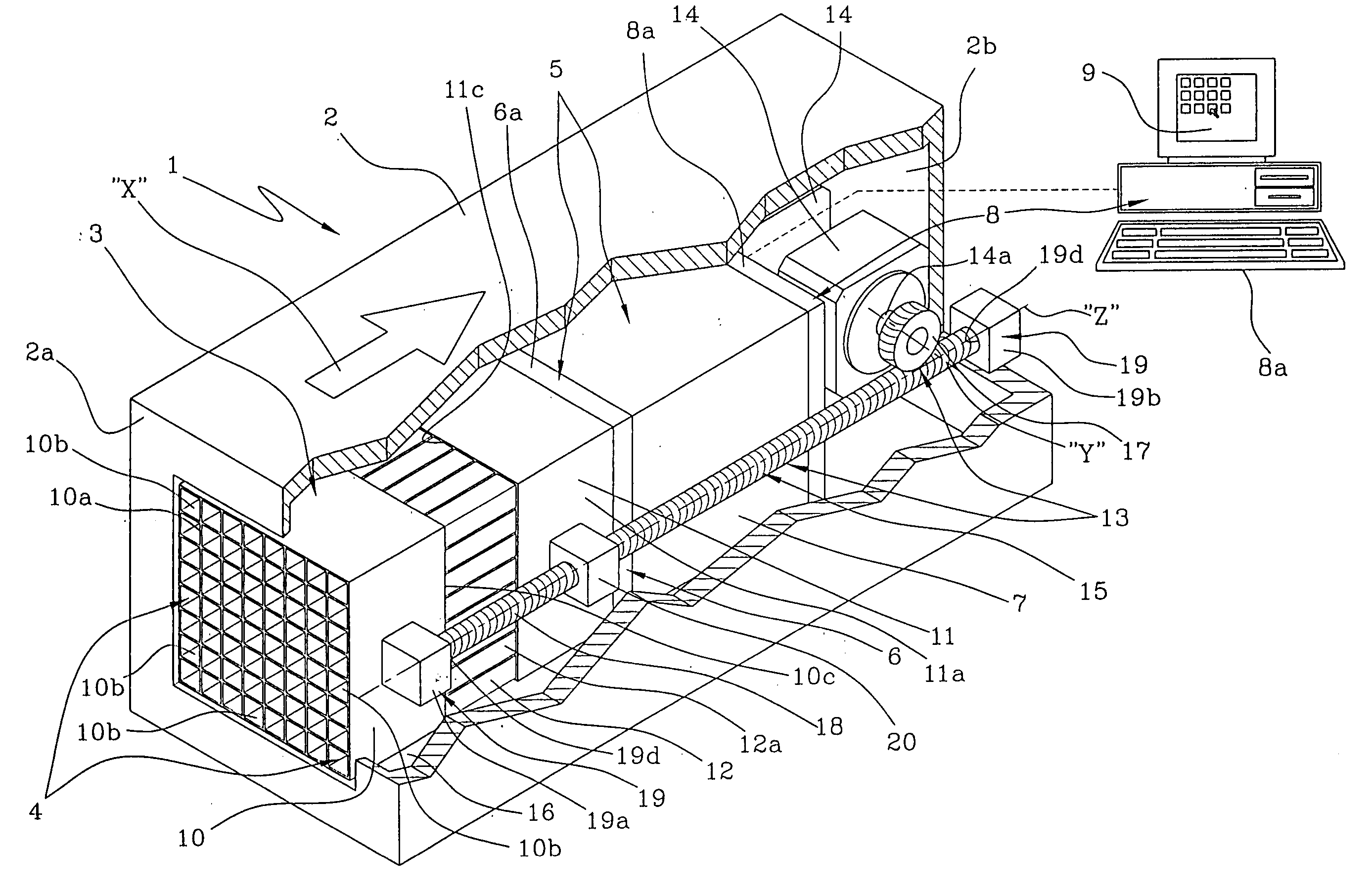
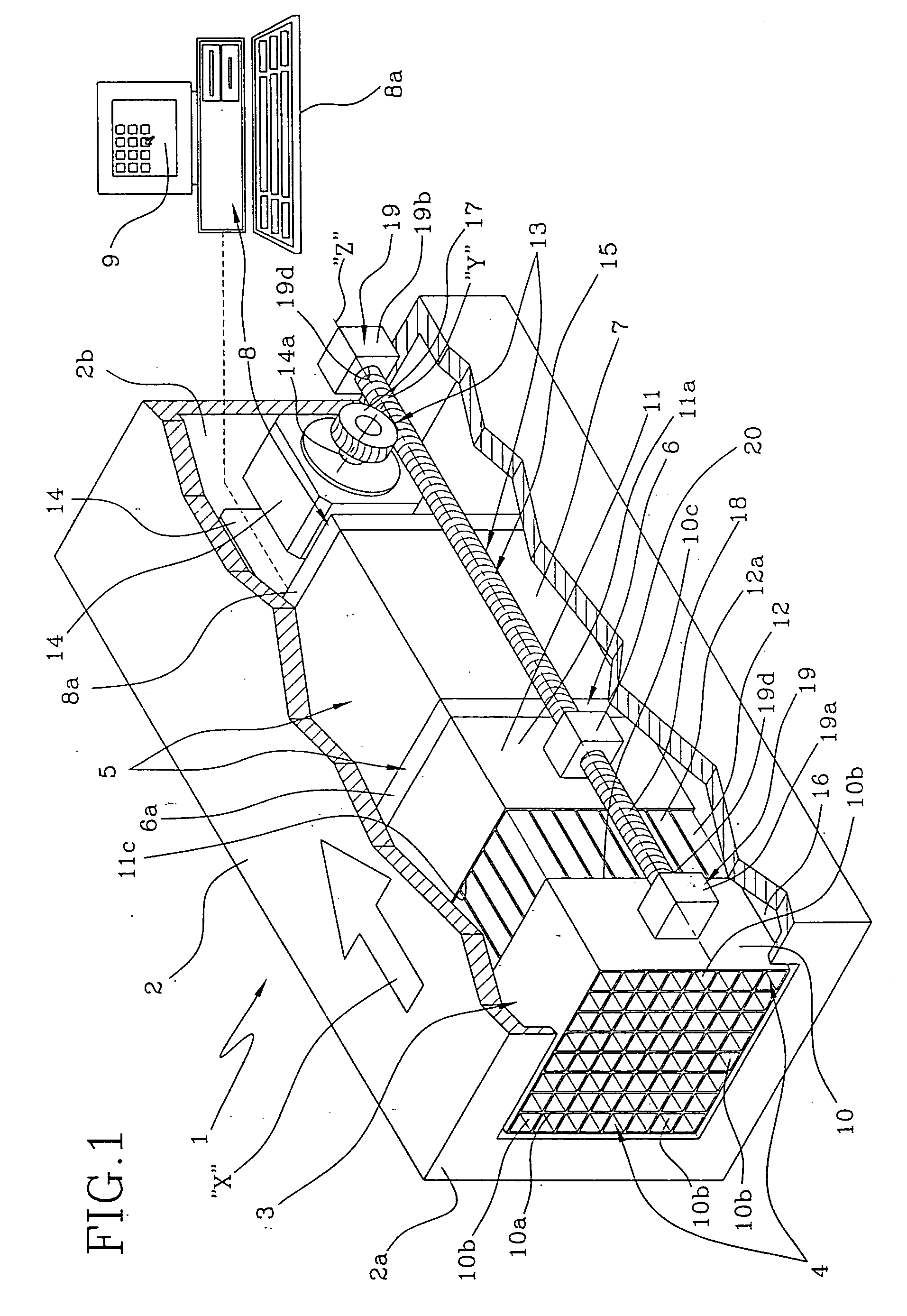
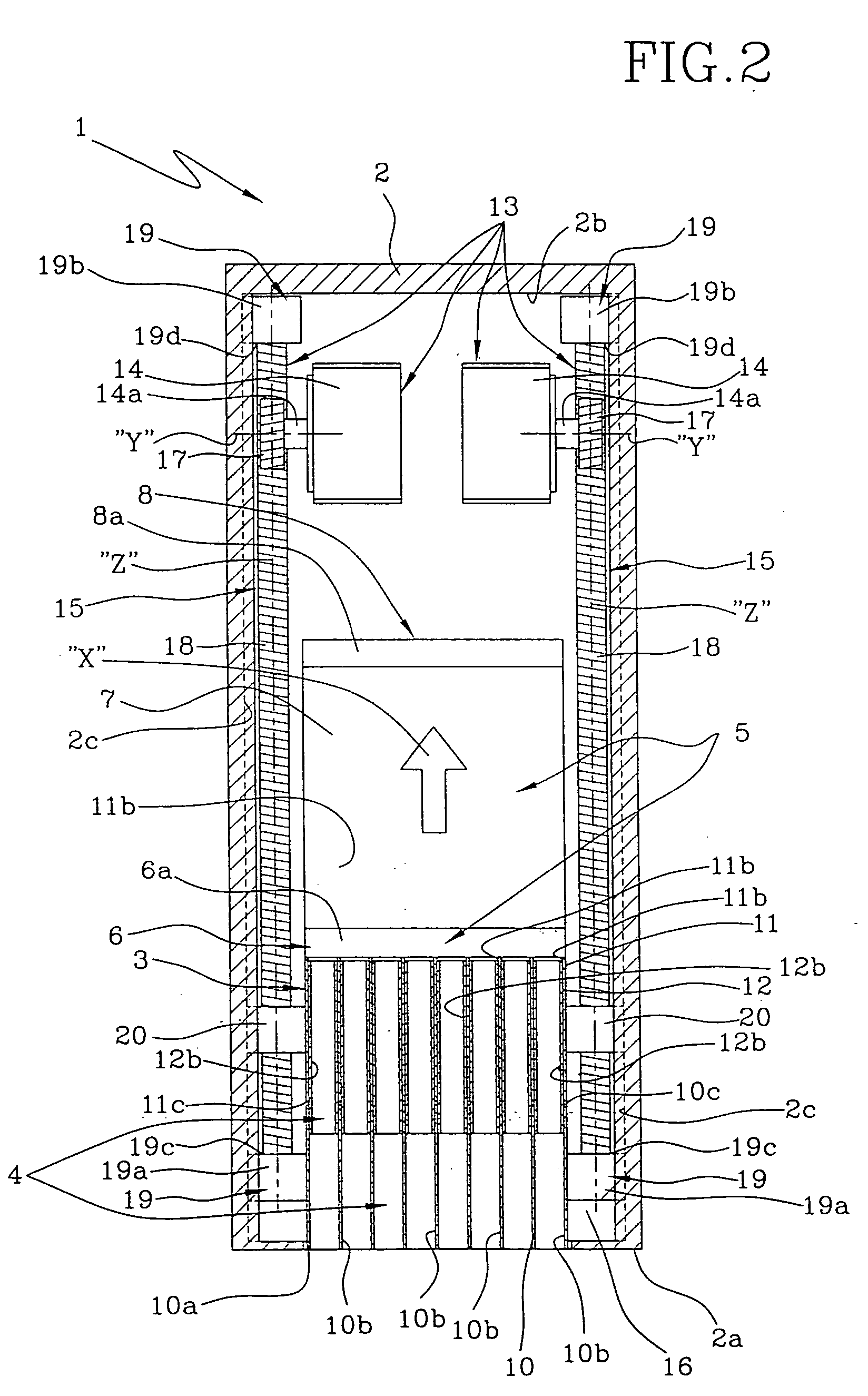
[0051] Both for the first embodiment and for the subsequent solutions, the main electric motors 14 and / or the actuating member 13 tasked with actuating the detection organ 5 and / or one or more blocks 10, 11, 12 of the collimator 6, can also be positioned outside the case 2 having different structural characteristics and movable components from those described.

[0052] In accordance with a second embodiment of the present invention illustrated in FIGS. 4-7, the intermediate 12 of the collimator 3 is operatively engaged to the application block 10 at the opposite part with respective to the application end 2a of the case 2 and it is movable between a first position (FIG. 5), in which it is at least partially inserted inside the application block 10, and a second position (FIG. 6), in which the intermediate block 12 is positioned at a terminal edge 10c of the application block 10, lying on a plane that is substantially perpendicular to the direction of measurement “X” and oriented at the...

second embodiment

[0054] With reference to FIGS. 4-6, the actuating member 13 shown in the second embodiment differs from the actuating member 13 illustrated in the first one, due to the presence of an auxiliary actuating member 21 operatively interposed between the collimator 3 and the case 2 able to actuate the intermediate block 12 between the first and the second position.

[0055] Preferably, the auxiliary actuating member 21 comprises for each side of the collimator 3, an auxiliary electric motor 22 and respective transmission auxiliary means 23 operatively interposed between the auxiliary electric motor 22 and the intermediate block 12 of the collimator 3. In detail, the auxiliary transmission means 23 comprise at least one auxiliary gear wheel 24 with helical teeth keyed on an auxiliary drive shaft 22a projecting from the respective auxiliary electric motor 22. The auxiliary gear wheel 24 rotates integrally with the auxiliary drive shaft22a around an axis of rotation “W” substantially perpendicu...

fourth embodiment

[0068] In accordance with the present invention, shown in FIGS. 11-13, the collimator 3 differs from the collimators 3 of the other embodiments by the presence of a plurality of mutually equal inner blocks 11′, 11b″, mutually aligned according to the direction of measurement “X” and interposed between the application block 10 and the measuring member 5.

[0069] Similarly to the solutions described above, at least one of the inner blocks 11′, 11″ is integrally engaged to the measuring member 5 in such a way as to translate together with the member along the direction of measurement “X”. Moreover, the inner blocks 11′, 11″ are movable with respect to one another and with respect to the application block 10 between a condition of contraction (FIG. 12), in which each block 10, 11′, 11″ is in contact with at least one of the other blocks 10, 11′, 11″ to define a single block 28, and an expansion condition (FIG. 13), in which each block 10, 11′, 11″ is distanced from the block 10, 11′, 11″ ...


PUM


Abstract

A scintigraphic device includes a case open at an application end, and coated by a shielding shell; a collimator positioned inside the case, made of a material with high atomic number and high density and having a plurality of collimation channels extending mutually parallel according to a predefined direction of measurement; a measuring member positioned inside the case in proximity to the collimator and including a scintillation crystal for converting each ionizing radiation originating from a source in exam into light radiation, and at least one photosensor, for determining the energy and the position of each detected event. The measuring member and the collimator are relatively movable to increase and/or reduce the distance between the converter and the application end and consequently to vary the total length of the collimator. The collimator may include two or more blocks at least one of which is movable relative to the others.

Description

BACKGROUND OF THE INVENTION [0001] The present invention relates to a scintigraphic device of the kind comprising: a case open at an application end and coated with a shielding shell; a collimator made of a material with high atomic number and high density and having a plurality of collimation channels extending substantially parallel to each other according to a predefined direction of measurement, the collimator being positioned inside the case in such a way as to allow the passage of radiation directed substantially parallel to the direction of measurement; a measuring member positioned inside the case in proximity to the collimator and comprising at least one converter able to convert each ionizing radiation coming from a source in exam in light radiation and at least one photosensor for determining the energy associated to each event and its position in the visual field; at least one electronic processing unit operatively associated to the photosensor. [0002] The present invent...

Claims


Application Information

Patent Timeline
IPC IPC(8): G01T1/161
CPCA61B6/4258G01T1/161
Inventor SOLURI, ALESSANDROPIANO, MARCOSCAFE, RAFFAELESCOPINARO, FRANCESCO
Owner CONSIGLIO NAT DELLE RICERCHE
Why Eureka
Try Eureka