Heat-fixing unit and imaging apparatus

A thermal fixing and equipment technology, which can be applied to electrothermal devices, electrical recording process equipment using charge patterns, thermal switches, etc., and can solve problems such as low thermal conductivity and limited thermal responsiveness.

Active Publication Date: 2004-08-18
BROTHER KOGYO KK
View PDF1 Cites 7 Cited by
  • Summary
  • Abstract
  • Description
  • Claims
  • Application Information

AI Technical Summary

Problems solved by technology

[0006] However, in the thermostat disclosed in JP-B-6-008869, since the heating roller and the bimetal disk are not in contact with each other, the heat emitted by the heating roller is conducted to the bimetal disk through the air having low thermal conductivity. Improved thermal responsiveness

Method used


Image

  • Heat-fixing unit and imaging apparatus
  • Heat-fixing unit and imaging apparatus
  • Heat-fixing unit and imaging apparatus

Examples


Embodiment Construction

[0023] Preferred embodiments of the present invention will be described in detail with reference to the accompanying drawings.

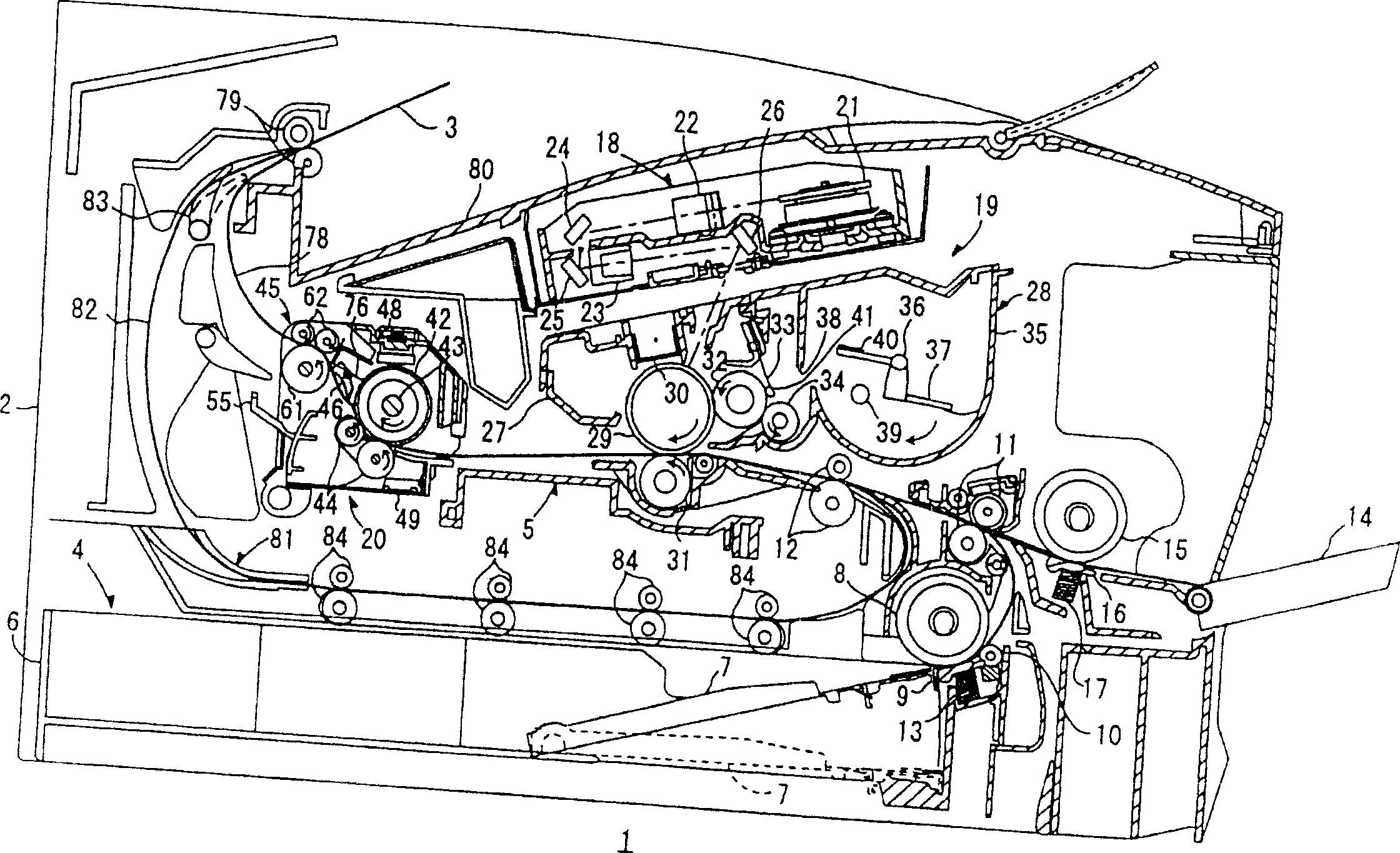
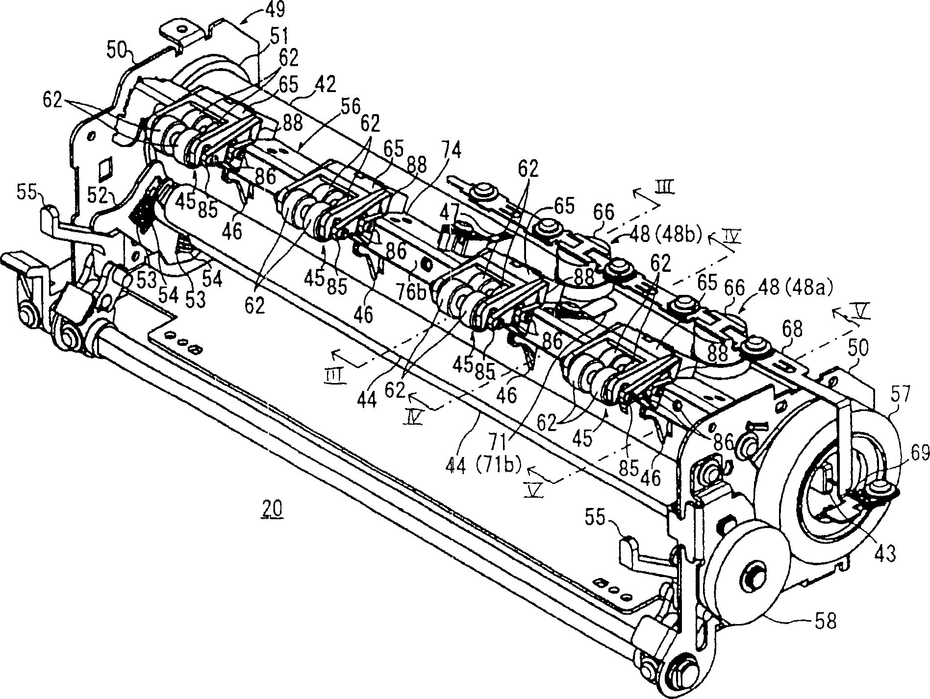
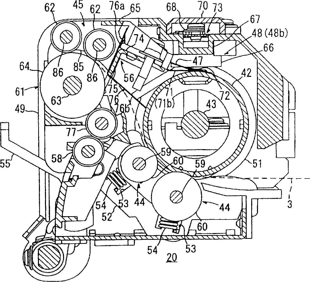
[0024] figure 1 is a main part side sectional view showing a preferred embodiment of a laser printer as an image forming apparatus according to the present invention. Such as figure 1 As shown, the laser printer 1 includes a paper feeding section 4 for feeding paper 3 as a fixing medium, an image forming section 5 for forming an image on the fed paper 3 , and other components in the main body casing 2 .

[0025] The paper feed section 4 includes a paper feed tray 6, a paper platen 7 provided in the paper feed tray, a paper feed roller 8 and a paper feed block 9 provided on one end of the paper feed tray 6, which is arranged opposite to the direction in which the paper 3 is conveyed. The paper scraps on the downstream side of the paper feed roller 8 (hereinafter, the downstream side of the conveying direction of the paper 3 is simply referred to as ...


PUM


Abstract

A heat roller with which a pressure roller is brought into press contact is rotatably supported by a bearing member made of a material which is softened when heated above a thermal fixation temperature, a thermostat in which a bimetal is exposed toward the heat roller is disposed at the opposite side of the heat roller with respect to the pressure roller, and a heat conduction member is made to intervene between the heat roller and the bimetal. According to the above configuration, the power supply to a fixation heater can be cut off by the thermal deformation of the bimetal. The heat roller is moved by softening of the bearing member, and the bimetal is mechanically deformed by pressing of the heat conduction member. Therefore, the power supply to the fixation heater can be cut off.

Description

technical field [0001] The present invention relates to a thermal fixing device and an image forming apparatus including the thermal fixing device. Background technique [0002] An image forming apparatus such as a laser printer is generally equipped with a heat-fixing device including a heat roller and a pressure roller, and when the paper passes through the heat roller and the pressure roller, the toner transferred to the paper is heat-fixed. [0003] The heating roller of the above-mentioned thermal fixing device generally includes a heater along its axis, and a heat cut-off device for preventing the heating roller from overheating due to the heater being placed around the heating roller. [0004] The above-mentioned thermal cutoff means is provided, for example, as a thermostat including a bimetal deformed by heat, and the bimetal is thermally deformed by overheating, thus cutting off power supplied to the heater. [0005] For example, it...

Claims


Application Information

Patent Timeline
Patent Type & Authority Applications(China)
IPC IPC(8): G03G15/20H01H37/04H05B1/02H05B3/00
CPCH01H37/043G03G15/2078G03G15/2039
Inventor 户松义也
Owner BROTHER KOGYO KK
Why Eureka
Try Eureka