An active gas generating method and apparatus thereof

A technology of active gas and generating device, applied in water supply device, electrical components, plasma, etc., can solve the problem that the surface is easy to be damaged

Inactive Publication Date: 2004-08-18
INST OF PHYSICS - CHINESE ACAD OF SCI
View PDF0 Cites 10 Cited by
  • Summary
  • Abstract
  • Description
  • Claims
  • Application Information

AI Technical Summary

Problems solved by technology

[0007] The purpose of the present invention is to overcome the main shortcomings of the existing dielectric barrier discharge device, such as the processed workpiece is in an uneven environment and its surface is easily damaged, and provide sufficient and appropriate active materials for the surface of the processed workpiece, thereby providing A method and device for generating active gas

Method used


Image

  • An active gas generating method and apparatus thereof
  • An active gas generating method and apparatus thereof
  • An active gas generating method and apparatus thereof

Examples


Embodiment 1

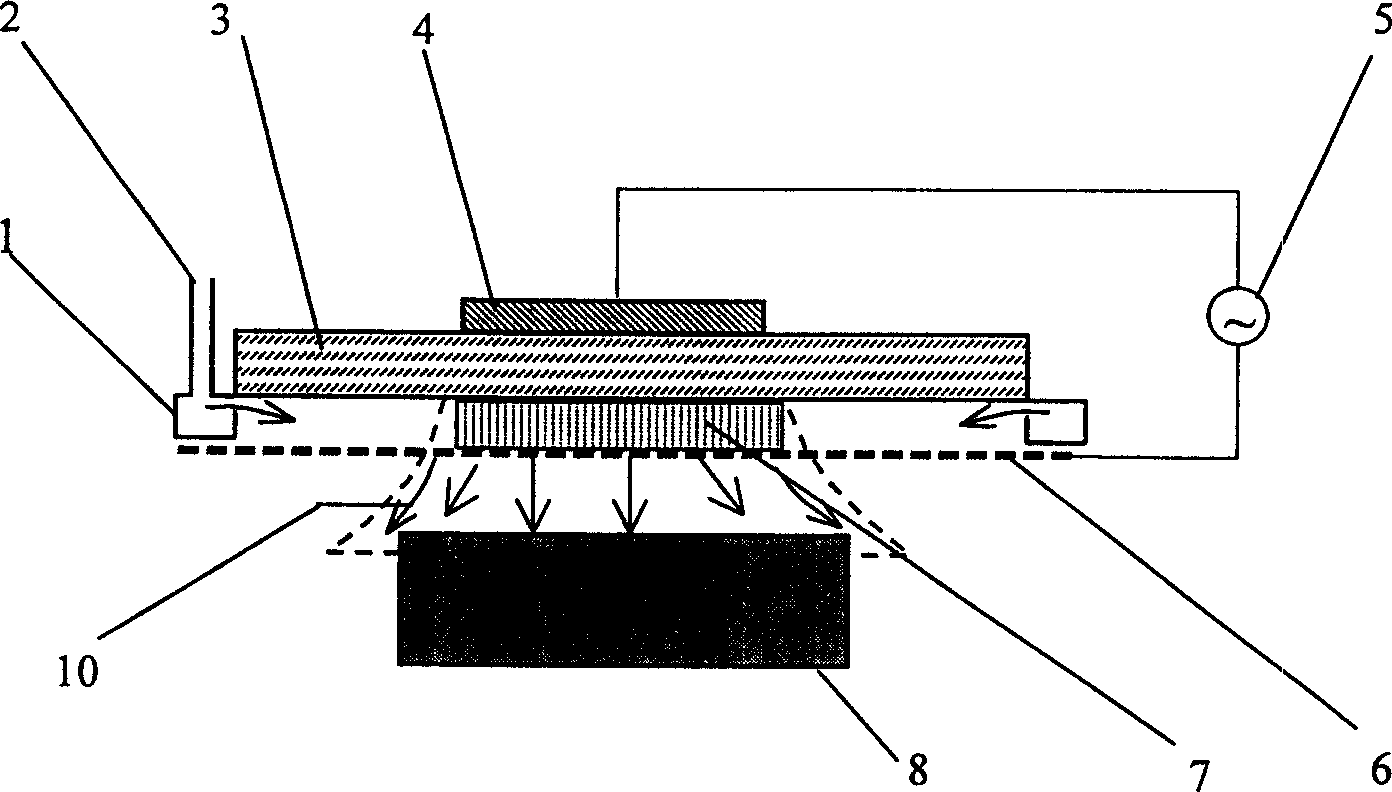
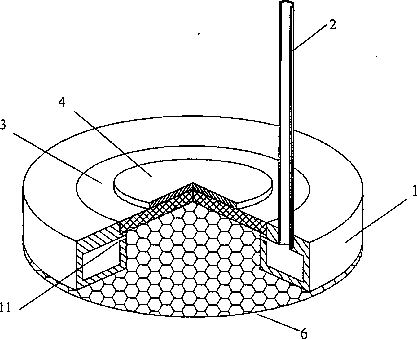
[0034] figure 1 Shown is a space discharge active gas generating device, including an alternating power supply 5 with an effective voltage of 8KV and a frequency of 30KHz. Its waveform can be sinusoidal, rectangular or other pulse waveforms, and its voltage is required to be between positive and negative Periodic changes. An output end of the alternating current power supply 5 is connected to the annular sheet-shaped upper electrode 4, and the lower surface of the upper electrode 4 is covered with an insulating dielectric sheet 3 with a thickness of 3 mm. The mesh lower electrode 6 is connected to the other output end of the alternating current power supply 5, and is placed under the insulating dielectric sheet 3 in parallel, with a distance of 5 mm from the insulating dielectric sheet 3. The mesh lower electrode 6 has mesh holes; discharge Zone 7 is between mesh electrode 6 and insulating dielectric sheet 3 . An annular gas supply channel 1 surrounds the discharge area 7 . ...

Embodiment 2

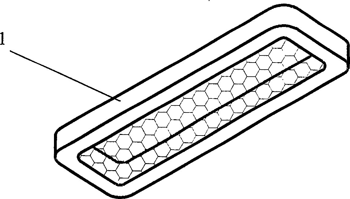
[0037] An active gas generating device in this embodiment is similar to that in Embodiment 1, and both adopt the space discharge type. The difference is that the air supply channel 1 is a rectangular closed air supply channel, such as image 3 shown. Figure 4 It is a cross-sectional view of the rectangular closed air supply channel in this embodiment.

Embodiment 3

[0039] Figure 5 It is an active gas generating device adopting surface discharge type or creeping discharge, which is similar to the device in Example 1. The difference is that the lower electrode 6 is a strip electrode. The strip-shaped bottom electrode 6 is in contact with the lower surface of the insulating dielectric sheet 3 , and the discharge area 7 is located around the strip-shaped bottom electrode 6 .

[0040] Surface discharge type electrodes can also be arranged in other ways, such as Figure 6 and Figure 7 shown. exist Figure 6 Among them, the upper electrode 4 is a sheet electrode, the lower electrode 6 is a block electrode, and the lower electrode 6 is in contact with the side of the insulating dielectric sheet. exist Figure 7 Among them, the strip-shaped lower electrode 6 and the strip-shaped upper electrode 4 adopt a coplanar structure, that is, the upper and lower electrodes are located on the same surface of the medium, and the upper and lower elect...


PUM

PropertyMeasurementUnit
thicknessaaaaaaaaaa
thicknessaaaaaaaaaa

Abstract

The invention discloses an active gas generation process and apparatus, wherein a medium blocking discharging mode is employed for electrical discharge, an air supplying duct is arranged around the discharging area for the medium blocking discharge, groove shape or porous air supplying openings are arranged on the side walls of the air supply duct with the air supply direction facing the discharge zone of the air supply port, a working gas is injected into the air supply duct which flows through the discharge zone for producing plasma and reactive neutral particles, the active gas containing the reactive neutral particles flows out of the discharge zone along with the air flow, finally arriving the surface of the processed work piece.

Description

technical field [0001] The invention relates to an active gas generation method and its device, in particular to a dielectric barrier discharge active gas generation method and its device with peripheral gas supply channels. Background technique [0002] Due to the simplicity of the setup and the possibility of working at atmospheric pressure, dielectric barrier discharge plasmas have received increasing attention. Dielectric barrier discharge is a non-equilibrium, alternating gas discharge. In the dielectric barrier discharge structure, at least one electrode surface is covered with a dielectric layer / sheet (it can also be covered with a dielectric layer / sheet on both electrode surfaces, or a dielectric sheet is inserted between the two electrodes), hence the name. Some people also call it silent discharge, or gas discharge controlled by the dielectric layer, or high-frequency discharge at atmospheric pressure, etc., based on different understandings of this discharge char...

Claims


Application Information

Patent Timeline
Patent Type & Authority Applications(China)
IPC IPC(8): A61L2/14C01B13/11H05H1/42
CPCA61L2202/23A61L2/14
Inventor 江南钱生法
Owner INST OF PHYSICS - CHINESE ACAD OF SCI
Why Eureka
Try Eureka