Magnetorheological continuously variable transmission

A continuously variable transmission, magnetorheological technology, applied in transmissions, friction transmissions, belts/chains/gears, etc., can solve the problems of high working voltage, insufficient performance, and low shear yield stress of electrorheological fluids

Inactive Publication Date: 2004-08-25
CHONGQING UNIV
View PDF7 Cites 27 Cited by
  • Summary
  • Abstract
  • Description
  • Claims
  • Application Information

AI Technical Summary

Problems solved by technology

In addition to the speed control device, the hydraulic viscous speed control system also needs a huge oil supply system and a complicated control device, which makes the whole speed control system bulky and expensive
However, the research on the application of electrorheological fluids in the field of continuously variable transmission, which was popular in the 1980s, shows that the shear yield stress of electr

Method used


Image

  • Magnetorheological continuously variable transmission
  • Magnetorheological continuously variable transmission

Examples


Embodiment Construction

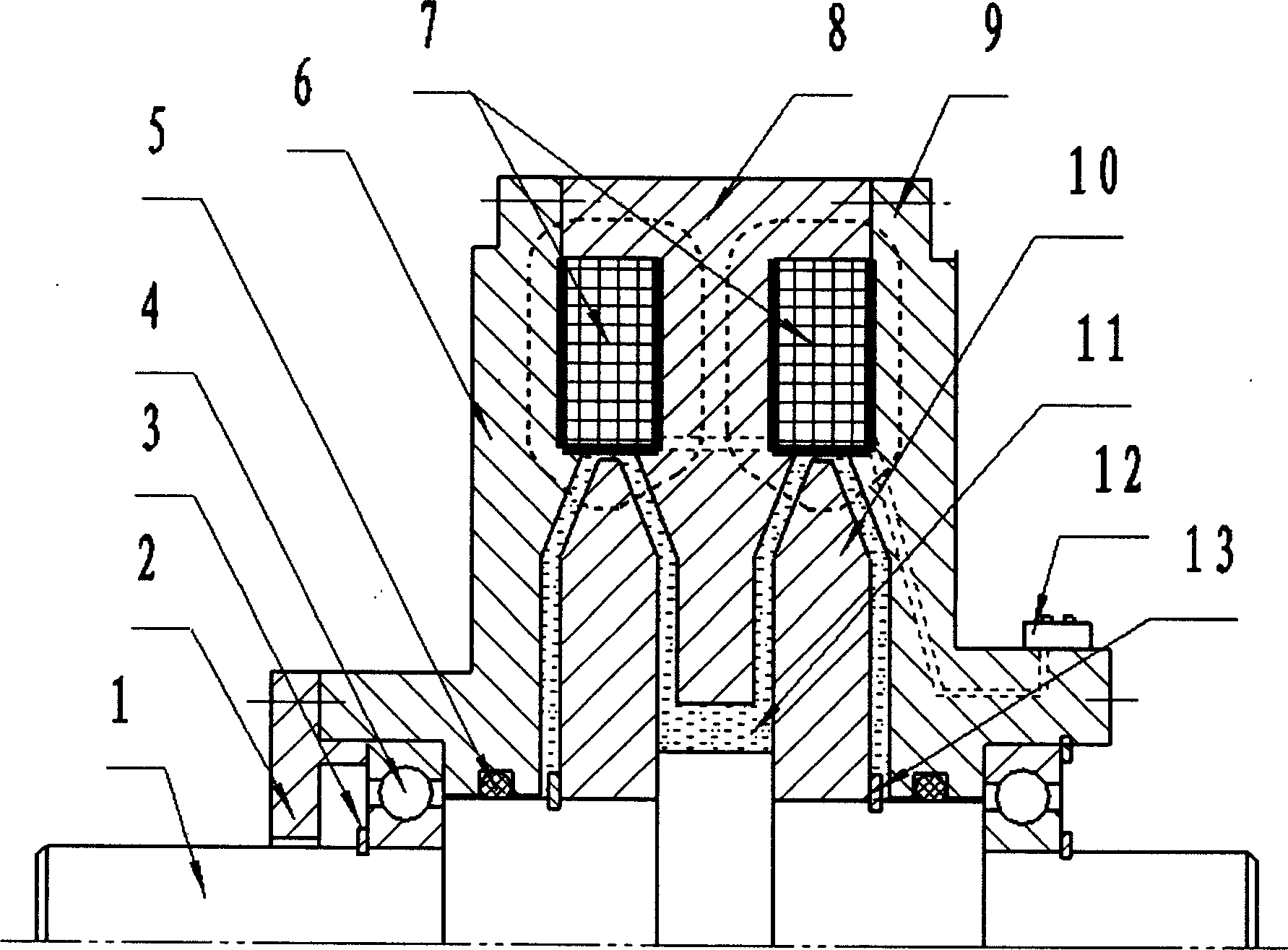
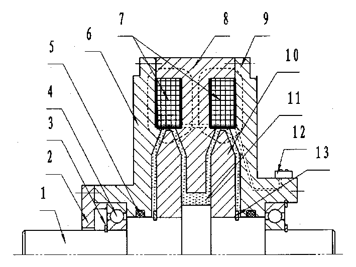
[0014] The input torque and rotational speed pass through the input shaft 1, the inner rotor disk 10, the torque is transmitted through the working medium 11 under the excitation magnetic field of the coil 5, and the load torque and rotational speed are output through the outer rotors 6, 8, 9. The right end of the outer rotor can be Connect to output connection parts such as standard flanges.

[0015] The input shaft 1 and two inner rotor discs 10 are fixedly connected together, the coil 7 is fixed in the outer rotor, and its excitation current is adjusted by an external adjustable DC power supply through a sliding brush 12 . The four radial slopes of the two inner rotor disks 10 and the inner surfaces of the outer rotor yokes 6, 8, and 9 form two V-shaped working gaps, and the magnetorheological fluid 11 fills the entire working chamber, and the seal on the outer rotor Ring 5 is sealed. The two inner rotor disks 10 are positioned axially by the middle shoulder of the shaft 1...


PUM


Abstract

The present invention relates to a magnetorheological stepless speed changer, and is characterized by that it includes inner rotor fixedly connected with input shaft, excitation coil fixed in the interior, outer rotor supported on the input shaft by means of two end bearings and working medium magnetorheological fluid filled in the V-shaped working gap between inner rotor and outer rotor, in which the input torque and rotating speed can be passed through input shaft and inner rotor and can utilize the magnetorheological effect produced by means of magnetorheological fluid working medium under the action of coil field to produce force moment transferring action so as to implement stepless changed load torque and rotating speed output by outer rotor.

Description

technical field [0001] The present invention relates to continuously variable transmissions or stepless speed regulators. Specifically, it uses magnetorheological fluid as the working medium to perform stepless adjustment of torque and speed between the input and output components. It can be used in electric bicycles, motorcycles and industrial low-power occasions and requires constant torque control, etc. Magneto-rheological stepless transmission for various occasions. Background technique [0002] The traditional liquid viscous transmission uses the viscosity of the liquid or the shearing effect of the oil film to transmit power. The working fluids usually used include Newtonian fluids such as lubricating oil, silicone oil, and hydraulic transmission oil. Generally, the method of adjusting the thickness of the oil film and the shearing area of ​​the oil film is adopted. to adjust the speed. In addition to the speed control device, the hydraulic viscous speed control syst...

Claims


Application Information

Patent Timeline
IPC IPC(8): F16H15/01
Inventor 梁锡昌蒋建东
Owner CHONGQING UNIV
Why Eureka
Try Eureka